Lighting device, illumination device, illumination apparatus and illumination system

a technology of illumination device and illumination device, which is applied in the direction of lighting apparatus, electrical equipment, light sources, etc., can solve the problems of taking time and effort to perform wiring work, and achieve the effect of simplifying construction work

Active Publication Date: 2015-04-02
PANASONIC INTELLECTUAL PROPERTY MANAGEMENT CO LTD
View PDF2 Cites 5 Cited by
  • Summary
  • Abstract
  • Description
  • Claims
  • Application Information

AI Technical Summary

Benefits of technology

[0007]In view of the above, the present disclosure provides a lighting device, an illumination device, an illumination apparatus and an illumination system capable of simplifying construction work.

Problems solved by technology

If it is intended to install additional wires in the existing houses or facilities, it is necessary to pass the wires through the back side of the wall, and it may take time and effort to perform the wiring work.

Method used


Image

  • Lighting device, illumination device, illumination apparatus and illumination system
  • Lighting device, illumination device, illumination apparatus and illumination system
  • Lighting device, illumination device, illumination apparatus and illumination system

Examples


first embodiment

[0026]A lighting device according to a first embodiment, and an illumination device, an illumination apparatus and an illumination system using the same will be described with reference to FIGS. 1 to 7.

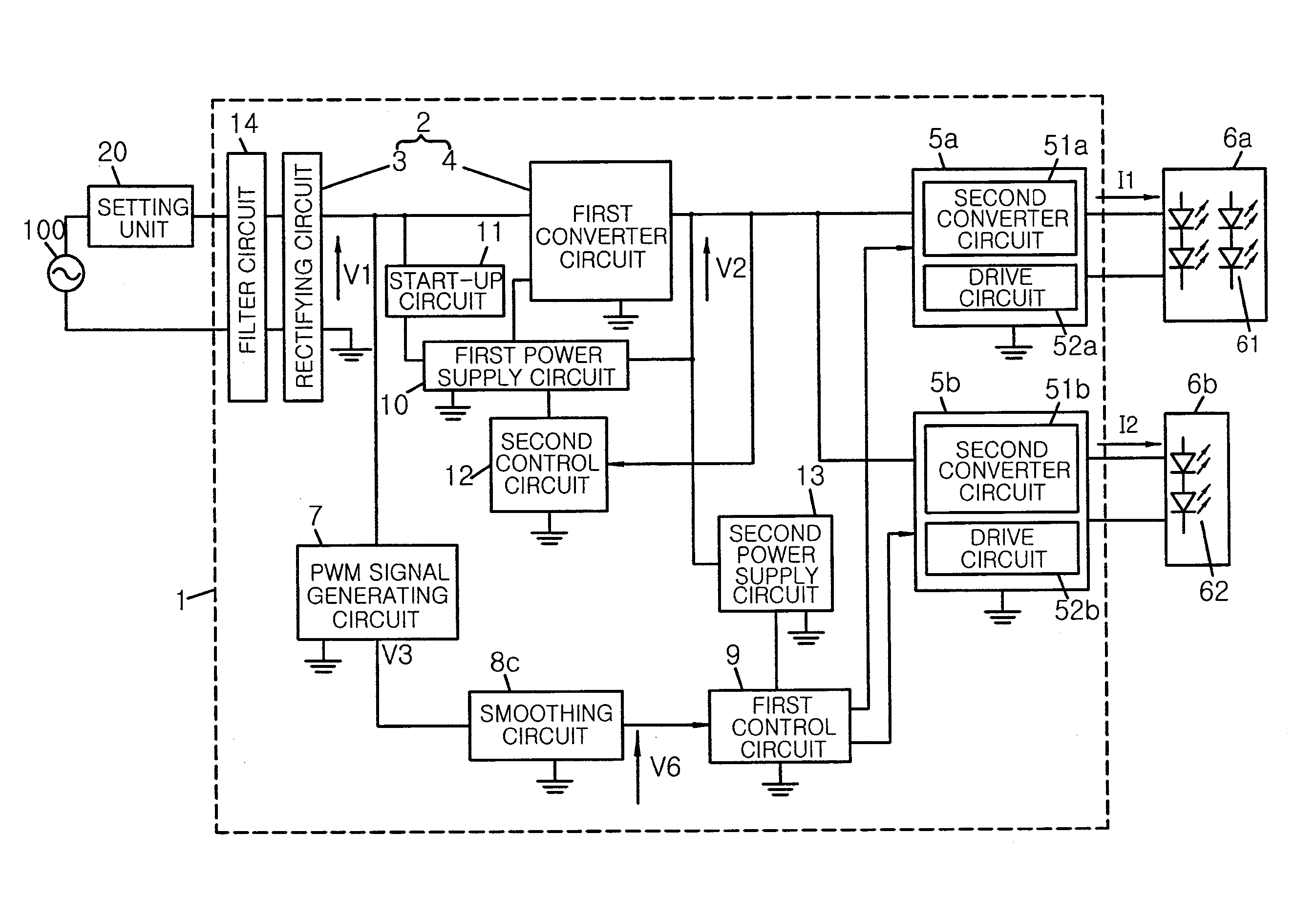
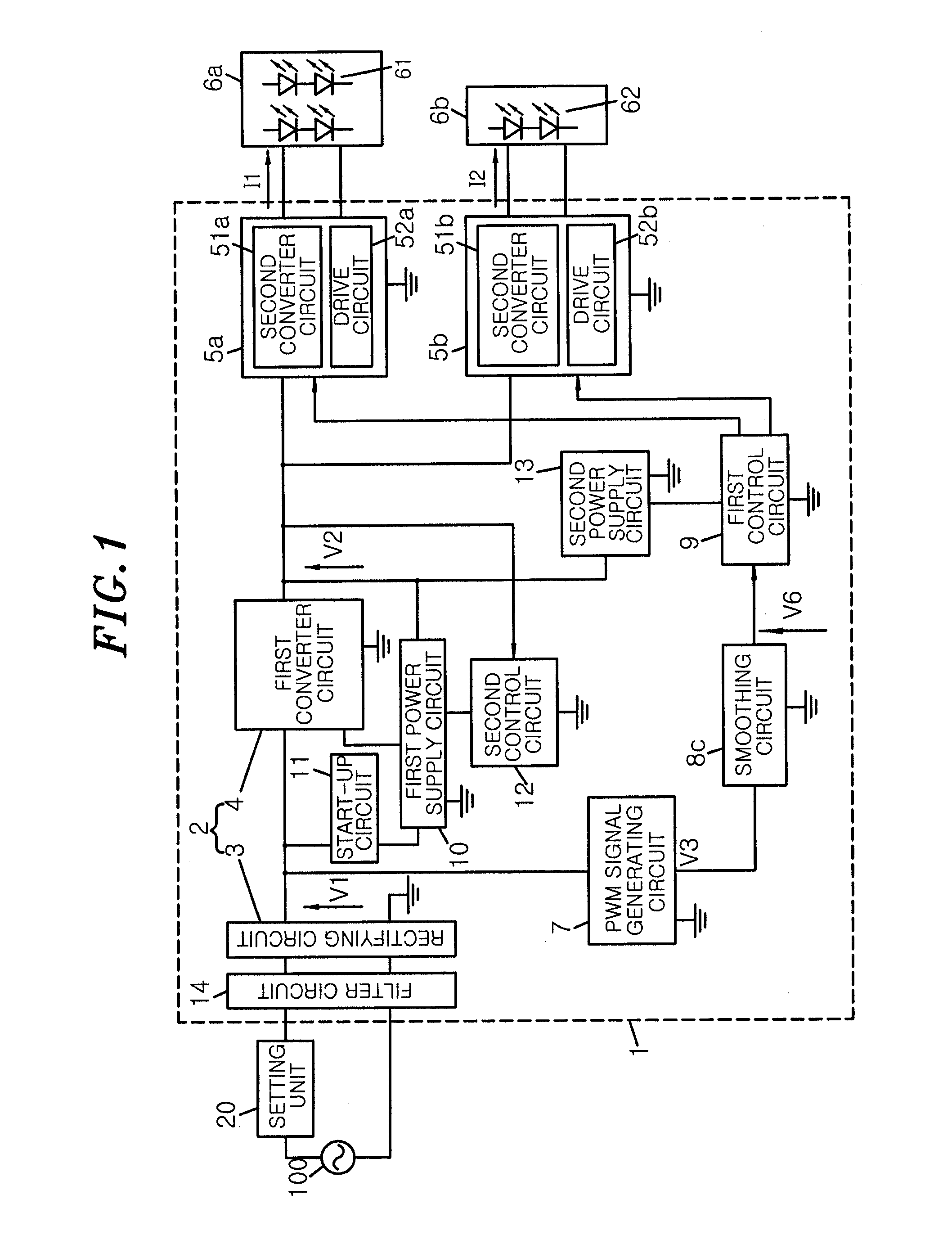
[0027]A lighting device 1 of the present embodiment includes, as shown in FIG. 1, an AC to DC conversion unit 2, second converter circuits 51a and 51b, a PWM signal generating circuit 7, a smoothing circuit 8c, and a first control circuit 9.

[0028]The lighting device 1 of the present embodiment further includes a first power supply circuit 10, a start-up circuit 11, a second control circuit 12, a second power supply circuit 13, a filter circuit 14, and drive circuits 52a and 52b. The lighting device 1 turns on light source modules 6a and 6b.

[0029]An AC power source 100 of AC 100V is connected to the input side of the filter circuit 14 through a setting unit 20. A rectifying circuit 3 is connected to the output side of the filter circuit 14.

[0030]The lighting device 1 of the present em...

second embodiment

[0103]A lighting device according to a second embodiment, and an illumination device, an illumination apparatus and an illumination system including the same will be described with reference to FIGS. 8 to 16.

[0104]As shown in FIG. 8, a lighting device 1A of the present embodiment includes an AC to DC conversion unit 2, second converter circuits 51a and 51b, a PWM signal generating circuit 7, smoothing circuits 8a and 8b, and a first control circuit 9. The lighting device 1A of the present embodiment further includes a first power supply circuit 10, a start-up circuit 11, a second control circuit 12, a second power supply circuit 13, a filter circuit 14, and drive circuits 52a and 52b. The lighting device 1A turns on and off light source modules 6a and 6b. The lighting device 1A of the present embodiment is different from the first embodiment in that it includes two smoothing circuits 8a and 8b, and in common with the first embodiment except for the difference. Thus, the same compone...


PUM


Abstract

A lighting device includes an AC to DC conversion unit for receiving a setting signal and converting it into a DC voltage having a predetermined voltage, voltage conversion units for converting the DC voltage inputted from the AC to DC conversion unit and driving the light source modules according to drive signals, a PWM signal generating unit for generating a PWM signal having a duty ratio corresponding to the setting signal, and a control unit, by outputting the drive signals to the voltage conversion units based on a command value determined according to the duty ratio, for controlling output powers of the voltage conversion units such that a characteristic curve of the sum of the output powers of the voltage conversion units has the maximum or at least one inflection point within an adjustment range of the conduction angle.

Description

CROSS-REFERENCE TO RELATED APPLICATION[0001]This application claims priority to Japanese Patent Application Nos. 2013-206583 and 2014-098025 filed on Oct. 1, 2013 and May 9, 2014, respectively, the entire contents of which are incorporated herein by reference.TECHNICAL FIELD[0002]The present disclosure relates to a lighting device, an illumination device, an illumination apparatus and an illumination system, and more particularly to a lighting device, an illumination device, an illumination apparatus and an illumination system capable of adjusting a color temperature or light quantity.BACKGROUND ART[0003]Conventionally, there has been proposed a lighting device including a power supply unit to adjust a color and a quantity of illumination light by adjusting the light quantity of each of a plurality of light emitting elements with different emission colors according to a dimming signal inputted from a controller (see, e.g., Japanese Unexamined Patent Application Publication No. 2013-...

Claims


Application Information

Patent Timeline
Patent Type & Authority Applications(United States)
IPC IPC(8): H05B33/08H05B44/00
CPCH05B33/0851H05B33/0809H05B33/0866H05B45/20H05B45/385H05B45/24
Inventor YAGI, SANAFUKUDA, KENICHINARUO, MASAHIRO
Owner PANASONIC INTELLECTUAL PROPERTY MANAGEMENT CO LTD
Why Eureka
Try Eureka