Slope supporting structure and construction method

A technology of supporting structure and construction method, which is applied in the direction of foundation structure engineering, excavation, construction, etc., can solve the problems that the supporting structure cannot fully meet the requirements of slope support and the emergency treatment of the deformed slope, etc. The effect of avoiding difficulty in position, reasonable force and convenient construction

Pending Publication Date: 2020-06-19
CCTEG CHONGQING ENG CO LTD
View PDF0 Cites 1 Cited by
  • Summary
  • Abstract
  • Description
  • Claims
  • Application Information

AI Technical Summary

Problems solved by technology

[0003] The purpose of the present invention is to provide a slope support structure and construction method to solve the problem that the existing support structure cannot fully meet the requirements of slope support, especially the emergency management of deformed slopes.

Method used


Image

  • Slope supporting structure and construction method
  • Slope supporting structure and construction method

Examples


Embodiment 1

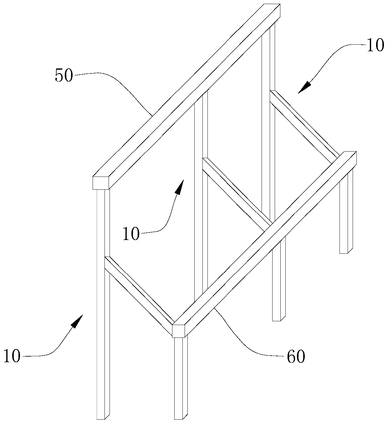
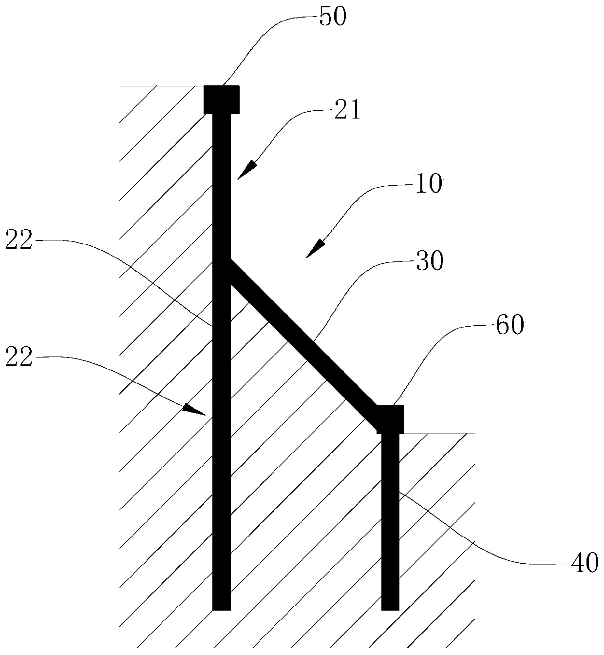
[0034] Please refer to figure 1 and figure 2 , a slope support structure, comprising: a plurality of support units 10 arranged at intervals in sequence. The support unit 10 includes vertical piles 20 , inclined beams 30 and pile foundations 40 . The vertical pile 20 extends downwards from the top of the slope, and the pile foundation 40 extends downwards from the bottom of the slope. The pile foundation 40 is connected. The tops of adjacent vertical piles 20 are connected by a top beam 50 , and adjacent pile foundations 40 are connected by a foundation beam 60 .

[0035] The vertical pile 20 includes a cantilever section 21 and an embedded section 22, the cantilever section 21 is located outside the slope crest, and the embedded section 22 is located in the soil layer. The top of the inclined beam 30 is connected to the joint between the cantilever section 21 and the embedded section 22 , and the bottom end of the inclined beam 30 is connected to the top of the pile found...

Embodiment 2

[0039] A construction method based on the slope support structure of embodiment 1, comprising the following steps:

[0040] S1: Drill a hole at the slope top of the side slope, and place a vertical pile 20 made of a steel pipe in the hole, and make the top of the vertical pile 20 outside the soil layer;

[0041] S2: Place a top beam 50 made of a steel pipe at the top of the adjacent vertical pile 20, and connect the two ends of the top beam 50 with the vertical pile 20 by bolts or by welding;

[0042] S3: drilling a hole at the bottom of the slope, and placing a pile foundation 40 made of steel pipes in the hole;

[0043] S4: Carry out grading and excavation along the inclined direction on the slope slope to form a placement groove, place an inclined beam 30 made of steel pipes in the placement groove, and connect the top of the inclined beam 30 to the vertical pile 20 by bolts or welding connection, since the inclined beam 30 extends along the inclination direction of the sl...

Embodiment 3

[0048] A construction method based on the slope support structure of embodiment 1, comprising the following steps:

[0049] S1: Drill a hole at the top of the slope, place a reinforcement cage in the hole, and make the top of the reinforcement cage outside the soil layer, reserve reinforcement along the slope at the position where the reinforcement cage contacts the soil layer, and place a reinforcement cage at the top of the reinforcement cage Reserving reinforcing bars on both sides, pouring concrete into the reinforcing cage at last, and forming vertical pile 20 after curing;

[0050] S2: Connect the reserved steel bars at the tops of the adjacent vertical piles 20 through steel bars, pour concrete, and form the capping beam 50 after curing;

[0051]S3: Drill a hole at the bottom of the slope, place a reinforcement cage in the hole, reserve reinforcement along the slope at the top of the reinforcement cage, reserve reinforcement on both sides at the top of the reinforcement...


PUM


Abstract

The invention discloses a slope supporting structure and a construction method, and belongs to the technical field of slope prevention and control. The slope supporting structure includes a pluralityof supporting units arranged at intervals. Each supporting unit comprises a vertical pile, an inclined beam and a pile foundation, wherein the two ends of the inclined beam are separately connected with the vertical pile and the pile foundation. The top ends of the adjacent vertical piles are connected through coping beams, and the adjacent pile foundations are connected through foundation beams.The slope supporting structure can effectively support a slope without need for large equipment, so that the problem that the large equipment is difficult to dispose in place or large disturbance is caused to the slope is avoided; compared with single-row or double-row micro piles, the slope supporting structure has the advantages that stress is more reasonable and the deformation resistance is higher; and compared with multi-row micro piles, the slope supporting structure has the advantages that the construction period is short and the cost is low.

Description

technical field [0001] The invention relates to the technical field of slope prevention and control, in particular to a slope support structure and a construction method. Background technique [0002] Due to the needs of engineering construction, the environment and foundation pit slope will be formed by excavation, and it is necessary to carry out support and treatment of the slope, especially the emergency treatment of the deformed slope is urgently needed. However, the use of conventional medium-sized and large-scale support piles, anchor rods, and anchor cables for support requires a long construction period, and it is difficult for large-scale machinery and equipment to enter the site or be in place or cause great disturbance to the slope; there is no space for grading with a stable slope rate. . The use of micro-pile construction progress is fast, the construction period is short, and small mechanical equipment is easy to enter and arrange. However, single-row or doub...

Claims


Application Information

Patent Timeline
Patent Type & Authority Applications(China)
IPC IPC(8): E02D17/20E02D27/12
CPCE02D17/20E02D27/12
Inventor 唐秋元邓继辉谢珂吴晓宁唐祯施毅
Owner CCTEG CHONGQING ENG CO LTD
Why Eureka
Try Eureka