Square multi-cavity steel plate-concrete composite floor

A combined floor and concrete technology, applied in floors, building components, buildings, etc., can solve the problems of large floor deflection, long construction period, and reduce the service life of components, etc., achieve strong lateral restraint, overcome crack exposure, and reduce production costs Effect

Inactive Publication Date: 2018-06-15
CHINA UNIV OF PETROLEUM (EAST CHINA)
View PDF0 Cites 0 Cited by
  • Summary
  • Abstract
  • Description
  • Claims
  • Application Information

AI Technical Summary

Problems solved by technology

[0002] At present, large supermarkets and shopping plazas, industrial and civil buildings, etc. are mainly cast-in-place concrete structures. This construction method has a long construction period and greatly affects the progress of the project. Construction noise and construction waste generated by construction will affect the daily life of surrounding people. Bring inconvenience, cause environmental pollution, increase social cost
Moreover, the traditional concrete components commonly used in buildings are heavy, which leads to excessive deflection of the floors of large supermarkets and shopping plazas. In order to reduce this situation, more steel bars must be arranged; at the same time, the traditional floor slabs have poor crack resistance and cracks are exposed, which reduces the use of components. years, on-site pouring has many construction procedures, requires maintenance, and has a long construction period, and is limited by the construction environment and climatic conditions; traditional concrete components cannot well restrain the lateral sliding of concrete when it is under force, so that it cannot give full play to the compressive strength of concrete strength; in addition, traditional concrete components need formwork support when pouring, and the formed concrete components themselves lack integrity, and the quality is not easy to control

Method used


Image

  • Square multi-cavity steel plate-concrete composite floor
  • Square multi-cavity steel plate-concrete composite floor
  • Square multi-cavity steel plate-concrete composite floor

Examples


Embodiment Construction

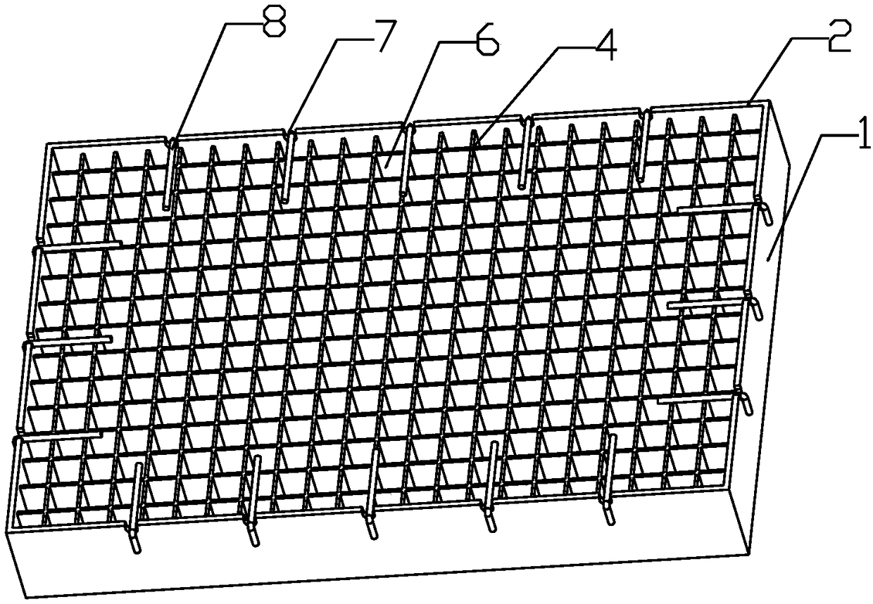
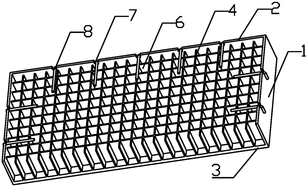
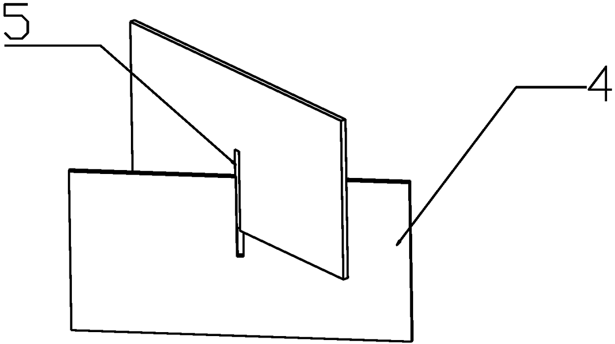
[0013] like figure 1 and 2 As shown, a square multi-cavity steel plate-concrete composite floor includes: a square multi-cavity space steel floor 1 and concrete, and concrete is poured in the square multi-cavity space steel floor 1 to form a combined integral member; wherein: square multi-cavity space steel The floor 1 is composed of a steel plate shell and a steel plate cavity 4 with a cutout 5. The steel plate shell is welded by four side wall steel plates 2 and one bottom steel plate 3 to form a cubic structure without a cover. The steel plate cavity 4 with a cutout 5 The upper and lower sides are cross-connected and welded in the steel plate shell to form a square multi-cavity steel floor 1, and concrete is poured in the steel floor 1 to form a square multi-cavity steel plate-concrete composite floor.

[0014] The height of the steel plate cavity 4 is lower than the steel plate shell, and the height difference between the two needs to be greater than the diameter of the n...


PUM


Abstract

The invention discloses a square multi-cavity steel plate-concrete composite floor, and belongs to the field of constructional engineering. The square multi-cavity steel plate-concrete composite floorcomprises a multi-cavity space steel floor and concrete; the concrete is poured into the square multi-cavity steel floor to form a combined integral component; the square multi-cavity steel floor iscomposed of a steel plate shell and steel plate cavities with notches; the steel plate is composed of five steel plates in a welding mode; the steel plate cavities with the notches are connected in aninserted mode up and down and welded in the steel plate shell to form the square multi-cavity steel floor; and the concrete is poured into the steel floor to form the square multi-cavity steel plate-concrete composite floor. The square multi-cavity steel plate-concrete composite floor has the beneficial effect that the problems of liable cracking and exposure cracking of traditional concrete components can be solved, the steel plate cavities have a high lateral restraining effect on the concrete, the compressive property of the concrete can be fully played, the self weight is light, the composite floor after molding has better overall performance, the steel plate shell replaces steel bars and structural steels in a traditional floor slab to play the role of the framework, the constructionoperation of traditional form erecting and form stripping is avoided, the square multi-cavity steel plate-concrete composite floor can replace a traditional framework in the construction site, the construction progress is increased, and the economic benefit is improved.

Description

technical field [0001] The invention belongs to the field of construction engineering, and in particular relates to the field of a square multi-cavity steel plate-concrete composite floor. Background technique [0002] At present, large supermarkets and shopping plazas, industrial and civil buildings, etc. are mainly cast-in-place concrete structures. This construction method has a long construction period and greatly affects the progress of the project. Construction noise and construction waste generated by construction will affect the daily life of surrounding people. It brings inconvenience, causes environmental pollution, and increases social cost. Moreover, the traditional concrete components commonly used in buildings are heavy, which leads to excessive deflection of the floors of large supermarkets and shopping plazas. In order to reduce this situation, more steel bars must be arranged; at the same time, the traditional floor slabs have poor crack resistance and crack...

Claims


Application Information

Patent Timeline
IPC IPC(8): E04B5/40
CPCE04B5/40
Inventor 李春宝马军张吉鑫张杨宜高富康高舒然周鹏坤
Owner CHINA UNIV OF PETROLEUM (EAST CHINA)
Why Eureka
Try Eureka