High-temperature-resistant grounding elastic piece and electronic equipment
A technology of high temperature resistance and elastic parts, applied in the direction of circuit, connection, fixed connection, etc., can solve the problem of conflicting integration of electronic components and high temperature resistant grounding elastic parts, so as to overcome easy cracking, ensure normal integration, and overcome mutual integration. contradictory effect
- Summary
- Abstract
- Description
- Claims
- Application Information
AI Technical Summary
Problems solved by technology
Method used
Image
Examples
Embodiment 1
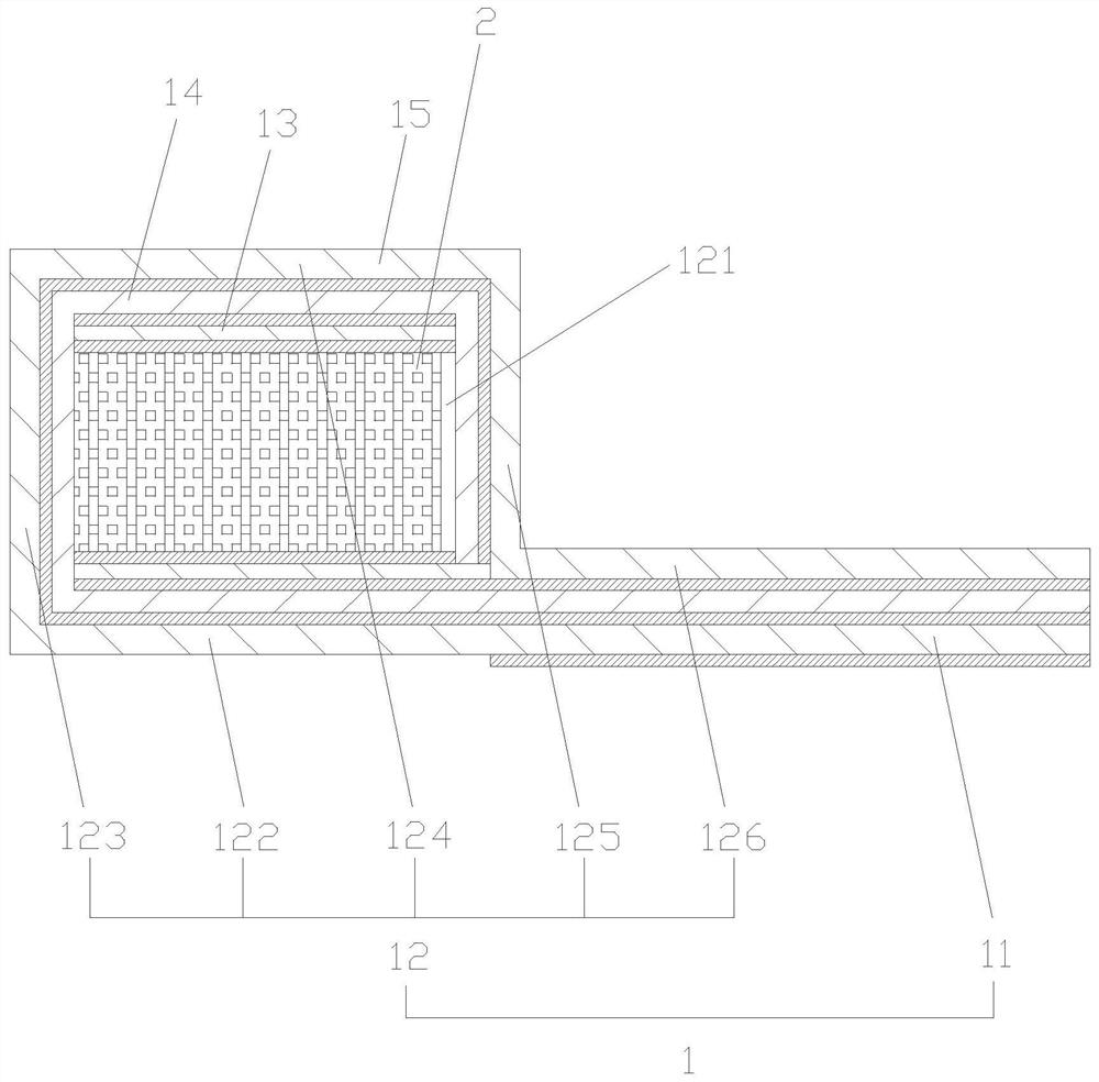
[0037] Such as figure 1 As shown, a high-temperature-resistant grounding elastic member includes: a conductive substrate 1 and a high-temperature-resistant elastic body 2 .
[0038] Preferably, the conductive substrate 1 is provided with a conductive part 11 and a covering part 12 . The covering part 12 is bent to form a cavity 121 for wrapping the high temperature resistant elastic body 2, the conductive part 11 is fixed to the covering part 12, and the conductive part 11 extends to the outside of the covering part 12, and extends to the Originally integrate the position of the high-temperature-resistant grounding elastic piece and form a corresponding electrical connection to ensure the normal use of the high-temperature-resistant grounding elastic piece. The length of the conductive part 11 is selected according to actual needs so that the high-temperature-resistant grounding elastic piece can be installed on the other locations.
[0039] Preferably, the cladding portion ...
Embodiment 2
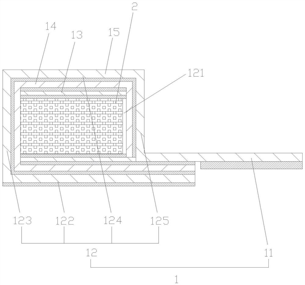
[0047] Such as figure 2 As shown, the difference between the second embodiment and the first embodiment is that the first connection section 122 , the second connection section 123 , the third connection section 124 , the fourth connection section 125 , and the conductive part 11 are sequentially connected as an integral structure. The connection between the first connecting section 122 and the conductive part 11 is fixed by glue. In actual use, the conductive part 11 is fixed with the integrated circuit board or the metal shell by welding, and the bottom of the conductive part 11 is provided with an adhesive layer for pasting and positioning. During welding, the adhesive layer will be broken down and will not affect the grounding elasticity. Compared with the traditional compression connection, the welding connection is more reliable.
Embodiment 3
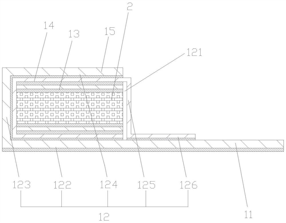
[0049] Such as image 3As shown, the difference between the third embodiment and the first embodiment is that the PI film layer 14 is provided with a fourth connecting section 125 and a fixing section 126 . The copper foil layer 15 of the covering part 12 is provided with a first connection section 122, a second connection section 123, and a third connection section 124, and the conductive part 11 is connected with the first connection section 122, the second connection section 123, and the third connection section 124. In an integrated structure, the conductive part 11 and the bottom of the first connecting section 122 are provided with an adhesive layer, and the fixed section 126 and the conductive part 11 are fixed by glue. In actual use, the conductive part 11 is fixed with the integrated circuit board or the metal shell by welding, and the bottom of the conductive part 11 is provided with an adhesive layer for pasting and positioning. During welding, the adhesive layer wi...
PUM
| Property | Measurement | Unit |
|---|---|---|
| Thickness | aaaaa | aaaaa |
| Thickness | aaaaa | aaaaa |
Abstract
Description
Claims
Application Information
 - R&D
- Intellectual Property
- Life Sciences
- Materials
- Tech Scout
- Unparalleled Data Quality
- Higher Quality Content
- 60% Fewer Hallucinations
Browse by: Latest US Patents, China's latest patents, Technical Efficacy Thesaurus, Application Domain, Technology Topic, Popular Technical Reports.
© 2025 PatSnap. All rights reserved.Legal|Privacy policy|Modern Slavery Act Transparency Statement|Sitemap|About US| Contact US: help@patsnap.com


