
Method for manufacturing composite grounding film and method and structure of high-temperature-resistant grounding elastic piece

A technology of composite grounding and elastic parts, which is applied in the direction of connection, electrical components, circuit/collector parts, etc., can solve the problems of easy cracking of surface coating and high production cost, and achieve high production cost, material saving, and easy cracking Effect

Active Publication Date: 2021-02-05
SHENZHEN JOHAN MATERIAL TECH CO LTD
View PDF16 Cites 0 Cited by
  • Summary
  • Abstract
  • Description
  • Claims
  • Application Information

AI Technical Summary

Problems solved by technology

[0003] The technical problem to be solved by the embodiment of the present invention is to provide a method and structure for making a composite grounding film and a high temperature resistant grounding elastic member to solve the problem of grounding elasticity The grounding film coating of parts cannot be electroplated into a spaced metal conductive layer, which leads to high production costs and technical problems that the surface coating is easy to crack

Method used


Image

  • Method for manufacturing composite grounding film and method and structure of high-temperature-resistant grounding elastic piece
  • Method for manufacturing composite grounding film and method and structure of high-temperature-resistant grounding elastic piece
  • Method for manufacturing composite grounding film and method and structure of high-temperature-resistant grounding elastic piece

Examples


Embodiment Construction

[0028] In order to fully understand the technical content of the present invention, the technical solution of the present invention will be further introduced and illustrated below in conjunction with schematic diagrams, but is not limited thereto.

[0029] If there are directional indications (such as up, down, left, right, front, back...) in the embodiments of the present invention, they are only used to explain the relative positions of the components in a certain posture (as shown in the drawings) relationship, motion, etc., if the particular pose changes, the directional indication changes accordingly.

[0030] In addition, in the present invention, the descriptions involving "first", "second" and so on are only for the purpose of description, and should not be understood as indicating or implying their relative importance or implicitly indicating the quantity of the indicated technical features. Thus, the features defined as "first" and "second" may explicitly or implici...


PUM

PropertyMeasurementUnit
thicknessaaaaaaaaaa
thicknessaaaaaaaaaa

Abstract

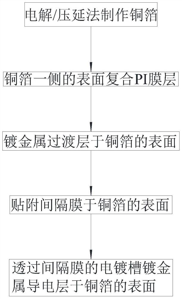
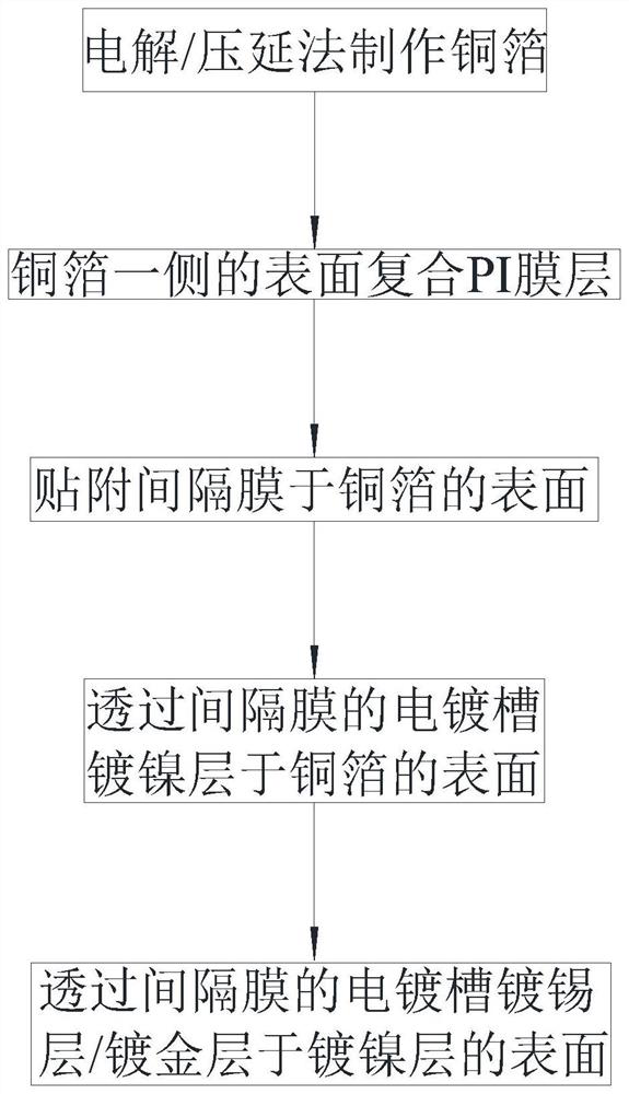
The invention relates to a method for manufacturing a composite grounding film and a method and a structure of a high-temperature-resistant grounding elastic piece. The invention discloses a method for manufacturing a composite ground film. The method comprises a film pasting step and an electroplating step, wherein the film pasting step comprises the following steps: attaching a separation film to the surface of the copper foil, wherein the spacing membrane is an insulator and is provided with spaced electroplating baths; the electroplating step comprises the step of plating a metal conducting layer on the surface of the copper foil through an electroplating bath of the spacing membrane. According to the utility model, the insulating spacer membrane is attached to the surface of the copper foil, and the spacer membrane is provided with the spaced electroplating baths, so that when the metal conducting layer is electroplated, the attached part of the spacer membrane cannot form the plated metal conducting layer, and the material of the plated metal conducting layer is saved. Therefore, by adopting the technical means of attaching the insulating diaphragm to the surface of the copper foil, the technical problem that the surface of the copper foil cannot be continuously electroplated into the spaced metal conducting layer in batches at low cost is solved, and the technical effectof saving precious metal conducting layer materials is achieved.

Description

technical field [0001] The invention relates to the field of conductive components, in particular to a method for making a composite grounding film and a method and structure for a high-temperature-resistant grounding elastic part. Background technique [0002] With the continuous development of integrated electronic technology, more and more electronic components are integrated in various electronic communication equipment, and the electronic components will interfere with each other during use. At present, under the dynamic working ground gap, electronic communication equipment basically adopts ground elastic parts or ground shrapnel to guide away electromagnetic waves or static electricity generated by electronic components. In the environment where the space is very compact and sensitive to stress, such as the consumer electronics industry, grounding elastic parts with less rebound stress are mainly used. The grounding elastic part is mainly composed of a grounding film...

Claims


Application Information

Patent Timeline
Patent Type & Authority Applications(China)
IPC IPC(8): H01R43/00C25D7/06
CPCH01R43/00C25D7/0614
Inventor 陈方刘晶云
Owner SHENZHEN JOHAN MATERIAL TECH CO LTD
Learn More