Adjustment device, system and methods

a technology of adjustment device and adjustment plate, applied in the direction of lighting support device, building repair, washstand, etc., can solve the problems and long manufacturing time of existing tools, and achieve the effect of long installation time, high raw material cost and long manufacturing tim

Active Publication Date: 2015-04-30
SIREK ANDY +1
View PDF6 Cites 3 Cited by
  • Summary
  • Abstract
  • Description
  • Claims
  • Application Information

AI Technical Summary

Benefits of technology

The solution reduces manufacturing and installation times, lowers raw material costs, and simplifies the alignment process, providing a cost-effective and efficient tool for aligning doors or windows with respect to frame structures.

Problems solved by technology

The inventors have realized the existing tools require relatively long manufacturing times due to precise machining operations, long installation times due to particular interactions of the known tools and high raw material costs due to numerous tool parts.
The inventors have realized that these detriments of existing window or door or extension jamb alignment tools are unneeded and undesirable in a tool.
Further, the inventive tool may also have low installation times due at least to simple interactions of the tool parts.

Method used


Image

  • Adjustment device, system and methods
  • Adjustment device, system and methods
  • Adjustment device, system and methods

Examples


Embodiment Construction

[0049]The subject inventive adjustment device and methods of using the adjustment device may take on numerous physical and methodical embodiments within the spirit of the invention and only preferred embodiments have been described in detail below, which are not meant to limit the scope or spirit or both of the invention.

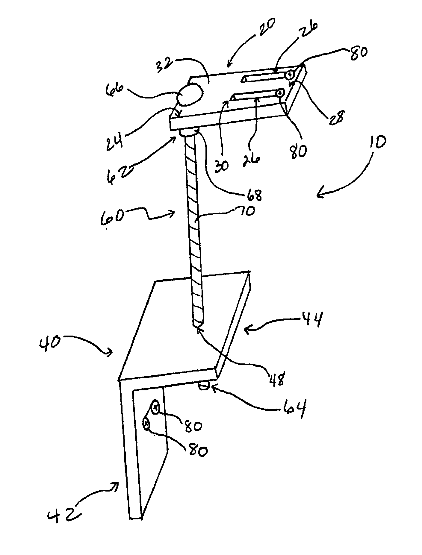
[0050]As shown in FIGS. 1-26, adjuster 10 may comprise guide 20, support 40 and connector 60. Guide 20 and support 40 may be independent of one another, which may mean they do not engage or interact directly except through connector 60. Further, adjuster 10 may also include attaching members 80. Attaching members 80 (of the same or differing sizes) may be utilized for attaching guide 20 to a frame 100 of a building or structure or other object; and for attaching support 40 to an extension jamb 120 of a door or window or other insert. Sometimes frame 100 (See FIG. 8, for instance) is referred to as a ā€œtrimmerā€ such as in the case of installing a window. Sometimes ext...


PUM


Abstract

An alignment device, systems and methods where the device includes a guide, a support and a connector which engages the guide and the support. The guide may be a relatively flat piece attachable to and edge of a frame for framing a window or a door. In one aspect the guide member a slot, support attaches to an object such as a window or a door (or is integral with an object such as a window or door) which is to be aligned with the frame. The connector threads within a hole associated with the object, such as a hole of a support connected to a jamb of a window. The connector engages a slot of the guide and the device allows for desired alignment of an object within a frame by transferring rotational movement to linear movement.

Description

[0001]The present application is a continuation-in-part of, and claims priority to, co-pending U.S. patent application Ser. No. 13 / 104,628, filed on May 10, 2011, which is a continuation-in-part of, and claims priority to, co-pending U.S. patent application Ser. No. 12 / 706,234, filed on Feb. 16, 2010, both of which are hereby incorporated by reference as if fully reproduced herein.BACKGROUND OF THE INVENTION[0002]1. Field of the Invention[0003]This invention is generally directed to an adjustment device. More particularly, the invention is directed to a device for adjusting objects within a frame.[0004]2. Background Information[0005]Doors and windows have been installed in buildings and structures since the invention of buildings and structures and the like. Sometimes the convention of installing doors or windows or other objects in structures includes guesswork as to where to rigidly set a door or a window or other object with respect to a frame structure.[0006]In a relatively rece...

Claims


Application Information

Patent Timeline
Patent Type & AuthorityApplications(United States)
IPC IPC(8): E04F21/00E06B1/04E06B3/96E06B1/60
CPCE04F21/0015E06B1/6015E06B3/96E06B1/04E06B1/6046
InventorSIREK, ANDYSIREK, COLTON
OwnerSIREK ANDY