Electrical Generator Apparatus, Particularly For Use On A Vehicle Roadway

a generator and vehicle technology, applied in the direction of electrical equipment, dynamo-electric components, dynamo-electric machines, etc., can solve the problems of inability to replace nearly as fast as they are being consumed, inability to use moving vehicles, and inability to meet the needs of moving vehicles, etc., to achieve efficient utilization and conservation of energy resources, reduce the demand load of the conventional power grid, and reduce the effect of consumption

Inactive Publication Date: 2015-04-30
JANG JACK SHIHZONG
View PDF11 Cites 8 Cited by
  • Summary
  • Abstract
  • Description
  • Claims
  • Application Information

AI Technical Summary

Benefits of technology

[0020]The electricity generated by the present invention can be used for powering devices, such as roadway lights, that would otherwise consume electrical power supplied by a conventional power grid. Thus, the demand load of the conventional power grid is reduced, which in turn, reduces energy resources that are consumed by the conventional power plant that supplies electricity to the conventional power grid. Accordingly, the electrical generator apparatus of the present invention materially contributes to the efficient utilization and conservation of energy resources by making more efficient use of the fuel that is consumed by vehicles, and by reducing the demand load of conventional power plants. By harnessing the kinetic energy of moving vehicles, the present invention advantageously provides a valuable, additional source of electrical power that would otherwise be unutilized.
[0021]In addition, the electrical generator apparatus described herein is an alternative, sustainable means of energy production. Unlike a conventional power plant, the electrical generator apparatus of the present invention is a “clean” technology that does not emit harmful waste products into the atmosphere as a byproduct of the power generation process. Consequently, the present invention also contributes to a reduction in greenhouse gas emissions by reducing harmful waste products that would otherwise by emitted from conventional power plants, which predominantly burn fossil fuels to generate electricity.

Problems solved by technology

Fossil fuels, such as coal, oil, and natural gas, take thousands of years to form naturally, and thus, cannot be replaced nearly as fast as they are being consumed.
While automotive manufacturers are actively developing technologies that are designed to increase the fuel efficiency of their vehicles (e.g., hybrid gas-electric vehicles), these technologies typically overlook one important source of additional energy, namely the energy that can be produced by the interaction between the vehicles and the roadway on which they travel.
Unfortunately, in the past, this vast source of free, sustainable energy from moving vehicles has rarely been utilized.
While others have designed different systems for extracting kinetic energy from moving vehicles, the related art devices have numerous limitations and drawbacks.
It is highly probable that the underutilization of the unused kinetic energy of moving vehicles can be attributed to the limitations present in the related art.
For example, some of these traffic-actuated systems employ complex fluid-based systems that are expensive and difficult to implement.
In addition, these fluid-based systems are not easy to maintain once they are installed within the roadway.
Other traffic-actuated systems of the related art employ elements that substantially deviate from the general contour of the roadway, and thus, disturb the natural flow of traffic by creating significant vehicle vibrations, as well as potentially creating a great deal of unrest when motorists pass thereover.
While such systems could be utilized in areas where only low speeds are generally encountered, such as parking lots, it is obvious that these systems would be unsuitable for any roadways on which vehicles are travelling at a high rate of speed, such as a freeway or highway, where the potential for harvesting energy produced by moving vehicles is the greatest.
Still other traffic-actuated systems taught by the related art utilize an arrangement of components that are readily susceptible to fatigue failure.
Because these gears will be subjected to millions of cycles in a region of high traffic, the gear teeth disposed on the outer surface thereof will likely undergo failure.

Method used


Image

  • Electrical Generator Apparatus, Particularly For Use On A Vehicle Roadway
  • Electrical Generator Apparatus, Particularly For Use On A Vehicle Roadway
  • Electrical Generator Apparatus, Particularly For Use On A Vehicle Roadway

Examples


first embodiment

1. First Embodiment

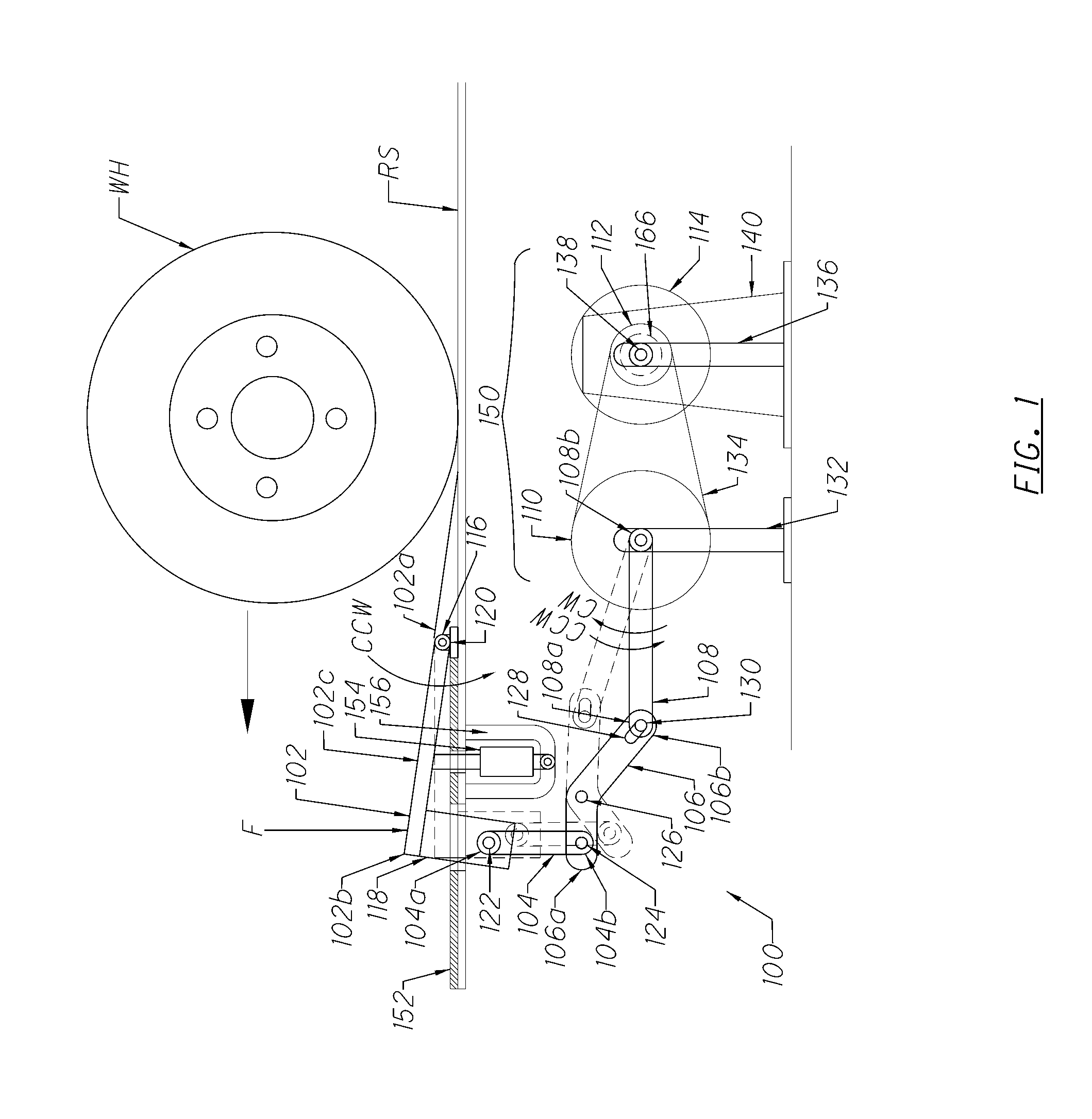
[0049]A first embodiment of an inventive electrical generator apparatus is seen generally at 100 in FIG. 1. In this embodiment, the electrical generator apparatus 100 generally comprises a rotatable top portion exemplified by rotatable lever portion 102, a first linkage member exemplified by plunger bar 104, a second linkage member exemplified by leverage bar 106, a third linkage member exemplified by crank 108, a first wheel 110, a second wheel 112, a flywheel 114, and an electrical generator 140. These components 102-140 are operatively coupled to one another such that electrical energy can be generated when an external actuation force F is applied to the rotatable lever portion 102 by a wheel WH of a vehicle traveling on a roadway surface RS. Each component of the system will be described in detail below.

[0050]In the first preferred embodiment of the invention, the rotatable lever portion 102 has a first end 102a, a second end 102b, and an upper surface 102c. A...

second embodiment

2. Second Embodiment

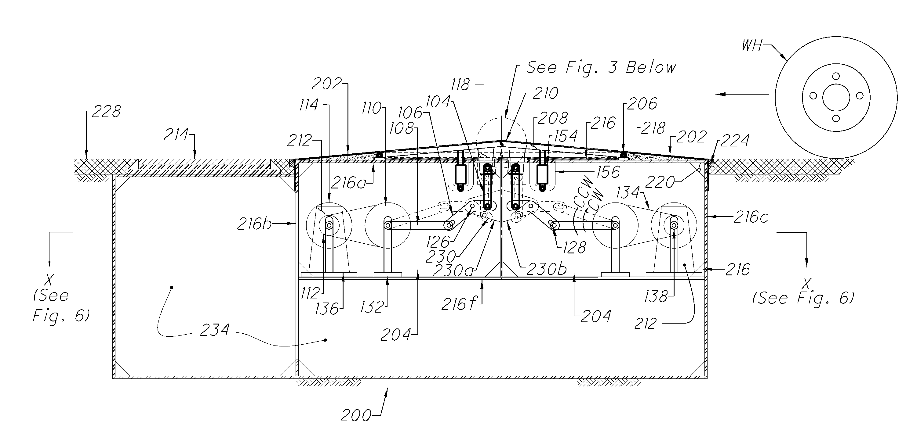
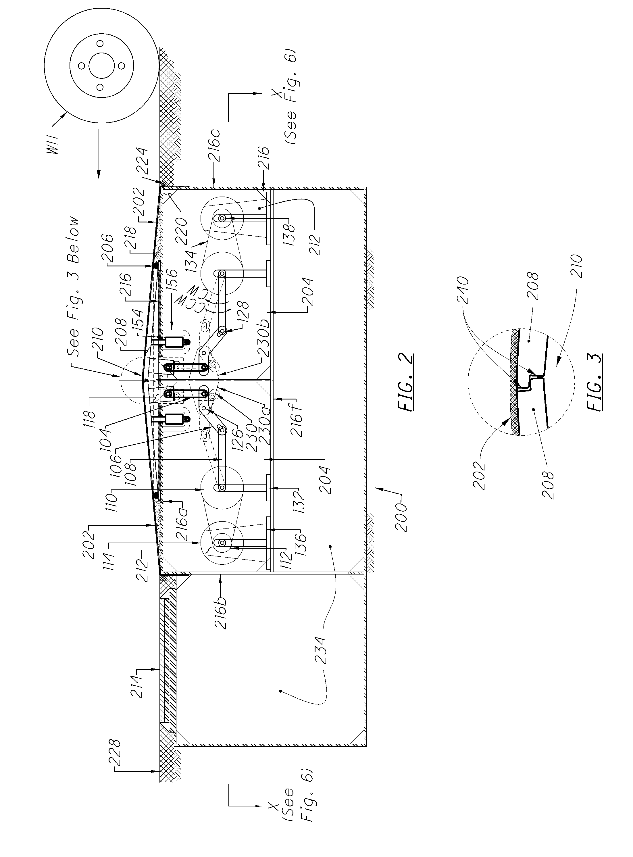
[0065]A second embodiment of an inventive electrical generator apparatus is seen generally at 200 in FIGS. 2 and 4-6. In some respects, the second embodiment is similar to that of the first embodiment. Moreover, some parts are common to both such embodiments. For the sake of brevity, the parts that the second embodiment of the electrical generator apparatus 200 has in common with the first embodiment of the electrical generator apparatus 100 will not described in conjunction with the second embodiment because these components have already been explained in detail above. Furthermore, in the interest of clarity, these components will be denoted using the same reference characters that were used in the first embodiment.

[0066]However, it is evident from FIGS. 2 and 4-6 that the second embodiment of the electrical generator apparatus 200 also differs in several important respects from that of the first embodiment of FIG. 1. The unique features of the second embodiment...

third embodiment

3. Third Embodiment

[0087]A third embodiment of an inventive electrical generator apparatus is seen generally at 400 in FIG. 13. The third embodiment is similar to that of the first embodiment, and in some respects, it is also similar to that of the second embodiment. Moreover, some parts are common to all three embodiments. For the sake of brevity, the parts that the third embodiment of the electrical generator apparatus (400) has in common with the preceding two embodiments of the electrical generator apparatus (100, 200) will not described in conjunction with the third embodiment because these components have already been explained in detail above. Furthermore, in the interest of clarity, these components will be denoted using the same reference characters that were used in the first two embodiments.

[0088]However, it is evident from FIG. 13 that the third embodiment of the electrical generator apparatus (400) also differs in several important respects from that of the first two em...


PUM


Abstract

An electrical generator system configured to convert an external actuation force applied by a vehicle traveling on a roadway into electrical energy is disclosed herein. The electrical generator system includes at least one electrical generator apparatus and a maintenance access assembly disposed adjacent to the at least one electrical generator apparatus. The maintenance access assembly includes a plurality of bounding walls defining a maintenance passageway for gaining service access to the at least one electrical generator apparatus. The maintenance access assembly further includes an access manhole disposed in an upper one of the plurality of bounding walls and above the maintenance passageway so as to facilitate access to the maintenance passageway.

Description

CROSS-REFERENCE TO RELATED APPLICATIONS[0001]This is a continuation-in-part of U.S. patent application Ser. No. 13 / 429,243, filed Mar. 23, 2012, which is a continuation-in-part of U.S. patent application Ser. No. 13 / 075,245, filed Mar. 30, 2011, which claims the benefit of U.S. Provisional Patent Application No. 61 / 463,477, filed on Feb. 17, 2011, the disclosure of each of which is hereby incorporated by reference as if set forth in their entirety herein.BACKGROUND OF THE INVENTION[0002]1. Field of the Invention[0003]The invention generally relates to electrical generating apparatuses. More particularly, the invention relates to an electrical generator apparatus that is designed to capture the otherwise wasted kinetic energy of moving vehicles travelling on a roadway, thereby resulting in the more efficient use of energy resources. The present invention materially contributes to the efficient utilization and conservation of petroleum-based energy resources by making better use of th...

Claims


Application Information

Patent Timeline
Patent Type & Authority Applications(United States)
IPC IPC(8): H02K7/18H02K7/06
CPCH02K7/06H02K7/1853F03G7/08
Inventor JANG, JACK SHIHZONG
Owner JANG JACK SHIHZONG
Why Eureka
Try Eureka