Imaging lens and imaging apparatus equipped with the same

a technology of imaging apparatus and lens, applied in the direction of optics, optical elements, instruments, etc., can solve the problems of severe requirements year after year, and achieve the effect of favorable optical performan

Active Publication Date: 2015-06-18
TIANJIN OFILM OPTO ELECTRONICS CO LTD
View PDF1 Cites 8 Cited by
  • Summary
  • Abstract
  • Description
  • Claims
  • Application Information

AI Technical Summary

Benefits of technology

[0005]The present invention has been developed in view of the circumstances described above, and it is an object of the present invention to provide an imaging lens formed compact, yet having a small F-number, a wide angle of view, and favorable optical performance. It is a further object of the present invention to provide an imaging apparatus equipped with the imaging lens.
[0019]According to the present invention, in an eight lens system composed of a front group and a rear group disposed in order from the object side, the power arrangement of the eight lenses and the shape of the most object side lens are set appropriately to satisfy given conditional expressions. This allows an imaging lens formed compact, yet having a small F-number, a wide angle of view, and favorable optical performance to be provided, as well as an imaging apparatus equipped with the imaging lens.

Problems solved by technology

Recently, lens systems that simultaneously satisfy wide angle of view, small F-number, compactness, and high performance have been demanded and the level of the requirements is getting severe year after year.

Method used


Image

  • Imaging lens and imaging apparatus equipped with the same
  • Imaging lens and imaging apparatus equipped with the same
  • Imaging lens and imaging apparatus equipped with the same

Examples


example 1

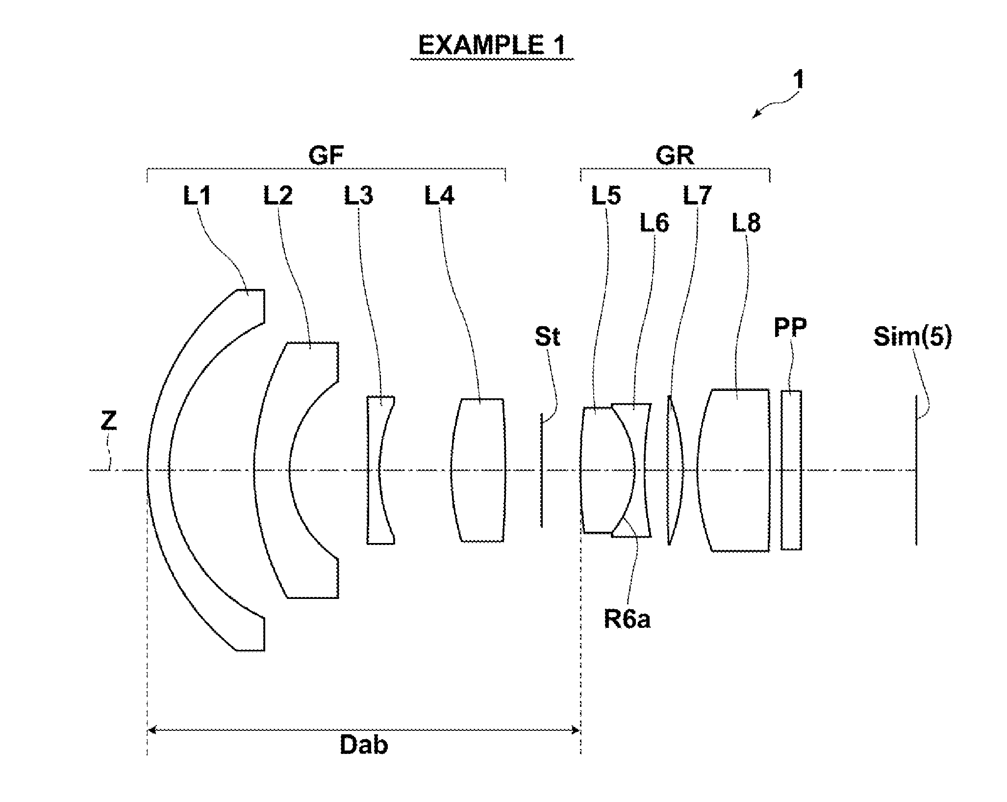
[0064]The lens cross-section view of the imaging lens of Example 1 is as illustrated in FIG. 1. As the illustration method is as described above, duplicated description will be omitted here.

[0065]The schematic configuration of the imaging lens of Example 1 is as follows. That is, the imaging lens consists of a front group GF having a negative refractive power, an aperture stop St, and a rear group GR having a positive refractive power, in order from the object side. The front group GF is composed of 4 lenses: a lens L1 having a negative meniscus shape with a convex surface on the object side; a lens L2 having a negative meniscus shape with a convex surface on the object side; a lens L3 having a biconcave shape; and a lens L4 having a biconvex shape, in order from the object side. The rear group GR is composed of 4 lenses: a lens L5 having a biconvex shape; a lens L6 having a biconcave shape; a lens L7 having a biconvex shape, and a lens L8 having a biconvex shape, in order from the ...

example 2

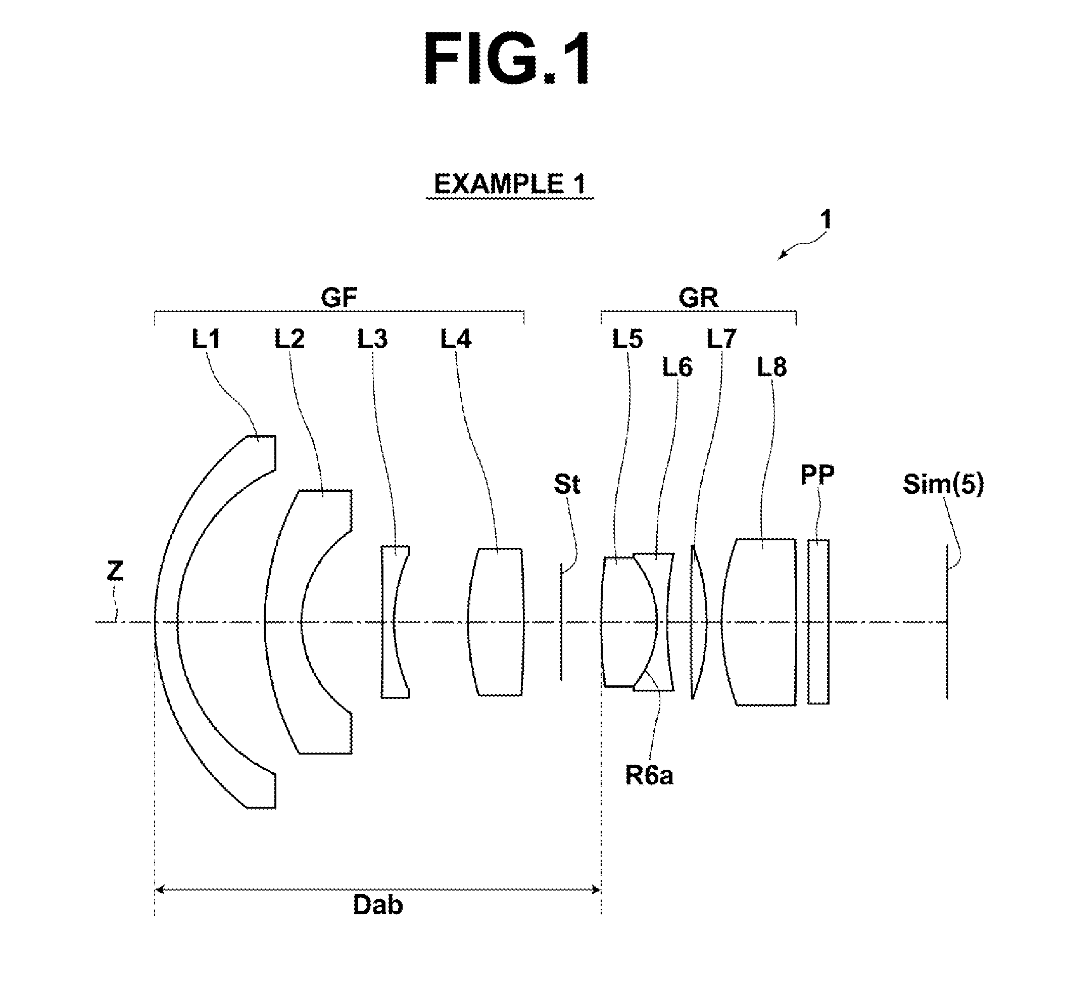
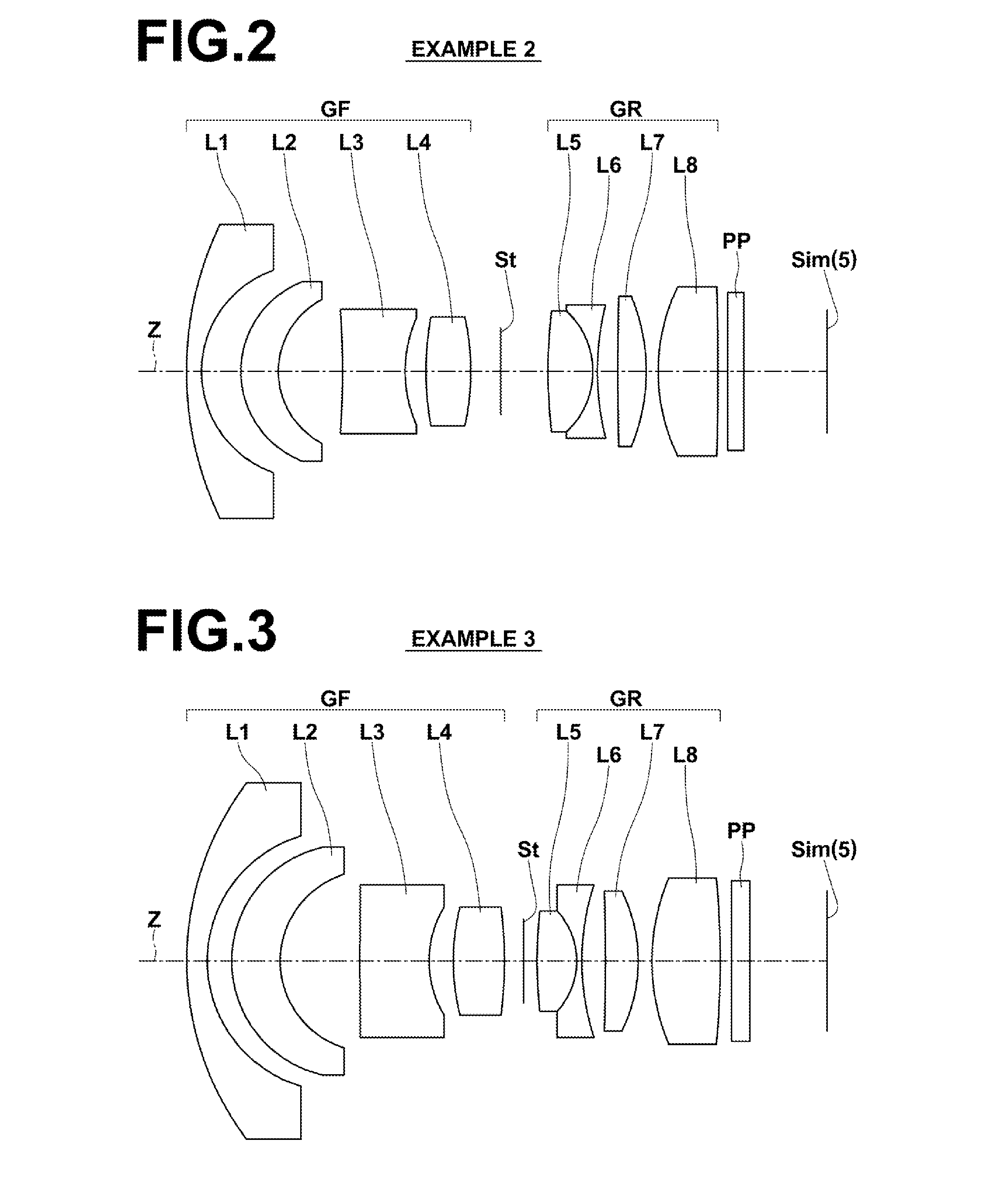
[0072]The lens cross-sectional view of the imaging lens of Example 2 is as illustrated in FIG. 2. The schematic configuration of the imaging lens of Example 2 is identical to that of Example 1. Table 2 shows lens data of the imaging lens of Example 2. A to D of FIG. 8 are respective aberration diagrams of the imaging lens of Example 2.

TABLE 2Example 2 Lens Dataf = 5.03, Bf = 6.94, FNo. = 1.60, 2ω = 97.0°SiRiDiNdjνdj 123.09091.001.4970081.54 27.24392.64 36.51962.511.6200436.26 45.50914.29 5−62.66654.191.6030065.44 68.89191.40 720.74123.001.8502632.27 8−16.83032.00 9 (St)∞3.171034.64303.001.8348142.7311−5.58660.301.8466623.781218.49161.3713211.25251.901.8348142.7314−13.40310.801513.07834.001.8348142.7316−217.48280.6717∞1.061.5163364.1418∞8.92

example 3

[0073]The lens cross-sectional view of the imaging lens of Example 3 is as illustrated in FIG. 3. The schematic configuration of the imaging lens of Example 3 is identical to that of Example 1, other than that the lens L3 has a negative meniscus shape with a convex surface on the object side and the lens L7 has a positive meniscus shape with a convex surface on the image side. Table 3 shows lens data of the imaging lens of Example 3. A to D of FIG. 9 are respective aberration diagrams of the imaging lens of Example 3.

TABLE 3Example 3 Lens Dataf = 4.99, Bf = 5.89, FNo. = 1.60, 2ω = 96.2°SiRiDiNdjνdj 117.49331.201.4970081.54 27.71601.43 36.91862.841.8466623.88 45.38154.67 5421.85044.051.5174252.43 66.20571.42 713.05093.001.8466623.88 8−24.30561.11 9 (St)∞0.801028.23342.321.8040046.5811−4.37990.301.8466623.881214.66441.3813−130.61391.921.8348142.7314−9.35010.801512.58454.001.8348142.7316−54.75380.6717∞1.061.5163364.1418∞4.52


PUM


Abstract

An imaging lens consists of a front group and a rear group. The front group is composed of a lens having a negative meniscus shape with a convex surface on the object side, a negative lens, a negative lens, and a positive lens in order from the object side. The rear group is composed of a positive lens, a negative lens, a positive lens, and a positive lens in order from the object side. The imaging lens satisfies given conditional expressions.

Description

CROSS-REFERENCE TO RELATED APPLICATIONS[0001]This application is a Continuation of PCT International Application No. PCT / JP2013 / 004894 filed on Aug. 19, 2013, which claims priority under 35 U.S.C. §119 (a) to Japanese Patent Application No. 2012-184980 filed on Aug. 24, 2012. Each of the above applications is hereby expressly incorporated by reference, in its entirety, into the present application.TECHNICAL FIELD[0002]The present invention relates to an imaging lens and an imaging apparatus equipped with the same, and more specifically to an imaging lens that can be used appropriately, for example, with digital cameras, broadcasting cameras, surveillance cameras, and vehicle cameras, and an imaging apparatus equipped with the imaging lens.BACKGROUND ART[0003]Heretofore, many wide angle lens systems which are applicable to the cameras in the foregoing fields and can be used in combination with solid-state image sensors have been proposed. Among them, as lens systems with eight to nin...

Claims


Application Information

Patent Timeline
Patent Type & Authority Applications(United States)
IPC IPC(8): G02B13/04G02B9/62G02B9/64
CPCG02B13/04G02B9/62G02B9/64G02B9/04G02B13/0045
Inventor SUN, PINGTSUTSUMI, KATSUHISACHO, MICHIO
Owner TIANJIN OFILM OPTO ELECTRONICS CO LTD
Why Eureka
Try Eureka