Shift control device and shift control method for vehicle

a technology of shift control and control device, which is applied in the direction of mechanical equipment, digital data processing details, instruments, etc., can solve the problems of not being able to determine the control operation amount, tie-up or racing of the rotating member, and not being able to execute control for temporarily varying the output torque of the driving force source, etc., to reduce the torque capacity of the released side engagement device, and quickly generate the differential rotation

Active Publication Date: 2015-09-17
TOYOTA JIDOSHA KK
View PDF7 Cites 4 Cited by
  • Summary
  • Abstract
  • Description
  • Claims
  • Application Information

AI Technical Summary

Benefits of technology

[0011]Here, in the shift control device according to the above aspect, the electronic control unit may be configured to, during a transition of the first shift, reduce the torque capacity of the released one of the engagement devices in the second shift as compared to that before a start of the first shift. With this configuration, when an excessive amount of the torque capacity of the released-side engagement device in the second shift remains at the time of changing from the first shift to the second shift, the released-side engagement device in the second shift cannot quickly generate differential rotation, a variation in the rotation speed of the rotating member on the input shaft side stops, and a shift shock may occur. However, by reducing the torque capacity of the released-side engagement device in the second shift during a transition of the first shift, an excessive remainder of the torque capacity of the released-side engagement device in the second shift at the time of changing into the second shift is avoided, and it is possible to quickly generate the differential rotation of the released-side engagement device in the second shift, so a shift shock is suppressed.
[0012]In the shift control device according to the above aspect, the electronic control unit may be configured to calculate a required value of the torque capacity of the released one of the engagement devices in the second shif

Problems solved by technology

With this configuration, in a situation that, when the three control operation amounts need to be determined in order to achieve the two shift target values, it is not possible to determine those control operation amounts unless a constraint condition is set.
Specifically, when only one of the torque capacity of the engaged-side engagement device and the torque capacity of the releas

Method used


Image

  • Shift control device and shift control method for vehicle
  • Shift control device and shift control method for vehicle
  • Shift control device and shift control method for vehicle

Examples


Embodiment Construction

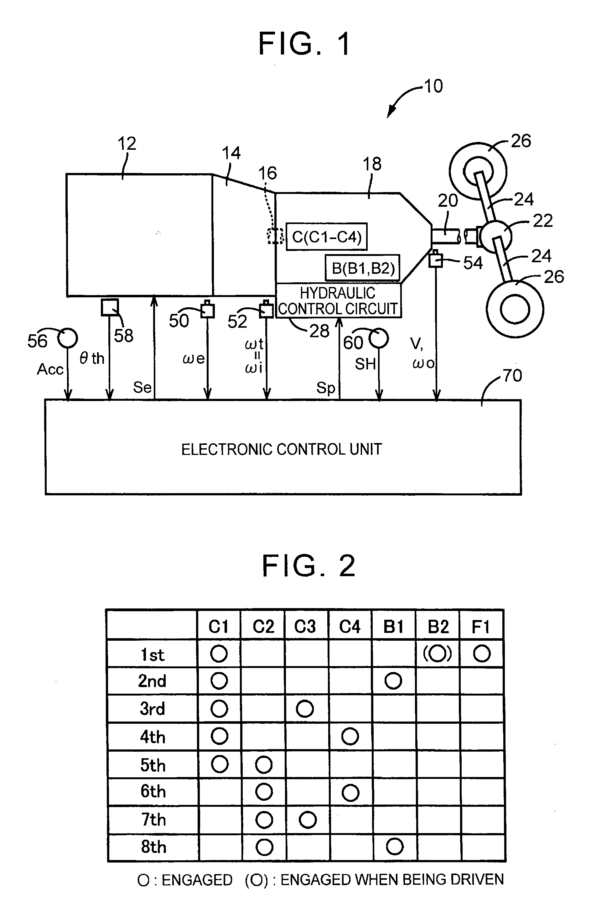
[0031]According to the invention, the vehicle, for example, may transmit power of the driving force source to the drive wheel via a power transmission device, such as the automatic transmission. In addition, the automatic transmission may be a step-gear automatic transmission in which a plurality of speeds (gear speeds) respectively having different speed ratios (gear ratios) are alternatively established by switching between engaged and released states of each of predetermined engagement devices. For example, the step-gear automatic transmission is a known planetary gear-type automatic transmission. Engagement devices, such as multi-disc or single-disc clutches and brakes that are engaged by corresponding hydraulic actuators and a hand brake, are widely used as engagement devices in the planetary gear-type automatic transmission. The vehicle, for example, may include a hydraulic control circuit that supplies hydraulic pressures to the hydraulic actuators of the plurality of engagem...


PUM


Abstract

Torque shares that express an exchange of torque are set as a constraint condition of an equation of motion of an automatic transmission, so it is suitable to control an exchange of torque between engagement devices, which is difficult in shift control, and it is possible to solve the equation of motion. In other words, it is possible to handle any shift pattern with the use of a predetermined shift model. Furthermore, at the time of a shift in which two elements are released and two elements are engaged, a first shift and a second shift in each of which one element is released and one element is engaged are carried out, so three control operation amounts are used in each of the first shift and the second shift, with the result that it is possible to solve the equation of motion.

Description

BACKGROUND OF THE INVENTION[0001]1. Field of the Invention[0002]The invention relates to a shift control device and shift control method for a vehicle, which execute shift control over an automatic transmission and, more particularly, to a technique for shifting the automatic transmission using a shift model.[0003]2. Description of Related Art[0004]There is well known an automatic transmission that includes a plurality of engagement devices, which transmit rotation and torque between an input shaft that receives power from a driving force source and an output shaft that transmits power to drive wheels, and that is shifted by causing each of the engagement devices to switch between an engaged state and a released state. Generally, in such an automatic transmission, a required value (that is, a control operation amount) of an element (for example, torque, or the like) that is operated for a controlled object is adapted for each gear speed while carrying out evaluations in an actual ve...

Claims


Application Information

Patent Timeline
IPC IPC(8): F16H61/02F16H61/686F16H61/04
CPCF16H61/0213F16H2061/0093F16H61/686F16H61/0437F16H61/061F16H2061/0455F16H2061/0451F16H2061/0081B60W10/11B60W10/06
Inventor MASUNAGA, SEIJIHASEGAWA, YOSHIOOTA, KEISUKE
Owner TOYOTA JIDOSHA KK
Why Eureka
Try Eureka