
Control device of vehicle

Active Publication Date: 2018-01-25
TOYOTA JIDOSHA KK
View PDF0 Cites 1 Cited by
  • Summary
  • Abstract
  • Description
  • Claims
  • Application Information

AI Technical Summary

Benefits of technology

The present invention provides a method for controlling the engagement of combustion engine gears in a multi-speed transmission during gear shifts. The delay control method includes setting a delay time for starting the torque phase of the gear shift, based on various factors such as the shared torque of the release-side engagement device, the torque capacity of the engagement-side engagement device, the frictional load of the engagement-side engagement device, and the hydraulic fluid temperature. The technical effect of this invention is to provide a more stable and efficient control method for gear shifts in multi-speed transmissions, leading to improved performance and reliability.

Problems solved by technology

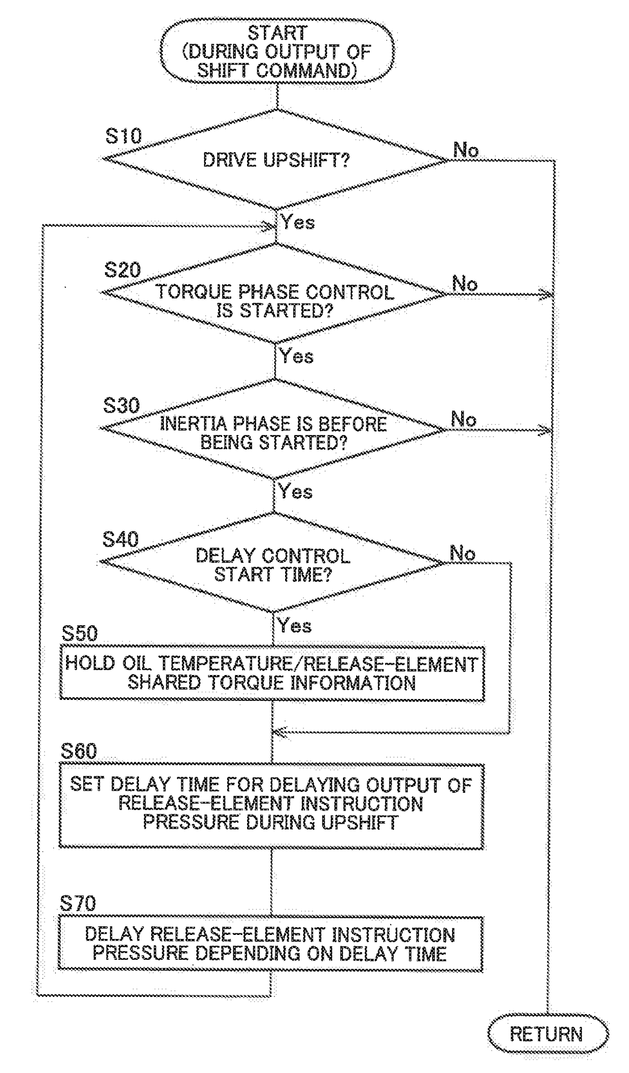
In Patent Document 1, it is disclosed that, when gears are shifted in an automatic transmission where the gear shifting is achieved by switching engagement and release of engagement devices, a transmission torque of a release-side engagement device (the engagement device to be released) starts decreasing before completing the packing of an engagement-side engagement device (the engagement device to be engaged), resulting in an insufficient total transmission torque of the engagement-side engagement device and the release-side engagement device possibly causing a shift shock and that, in this regard, by estimating a time required for the packing of the engagement-side engagement device based on oil temperature of the automatic transmission and by providing a temporal difference in timing of output between an increase start command for the transmission torque related to the engagement-side engagement device and a decrease start command for the transmission torque related to the release-side engagement device based on the time required for the packing, the shift shock due to the insufficient total transmission torque is suppressed.

Method used


Image

  • Control device of vehicle
  • Control device of vehicle
  • Control device of vehicle

Examples


example

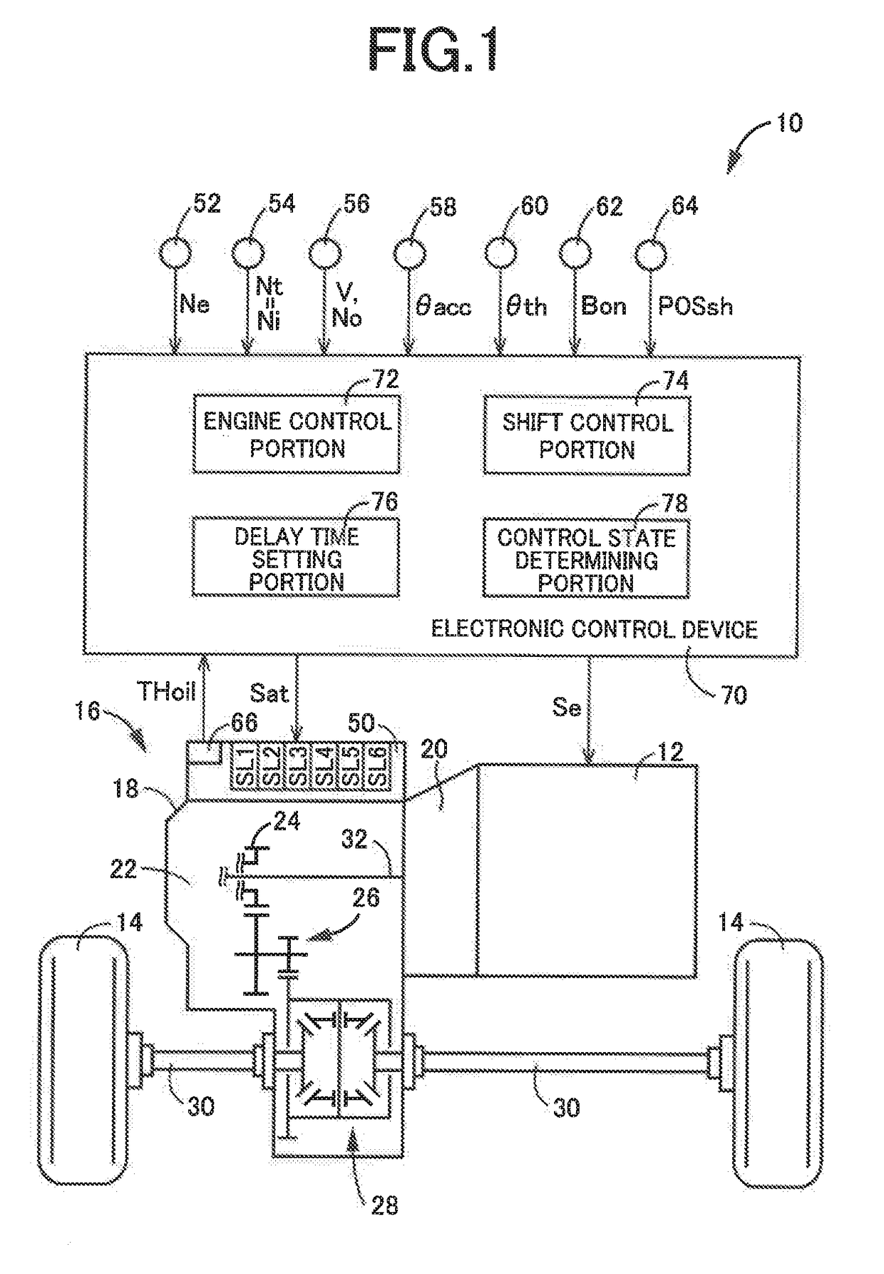
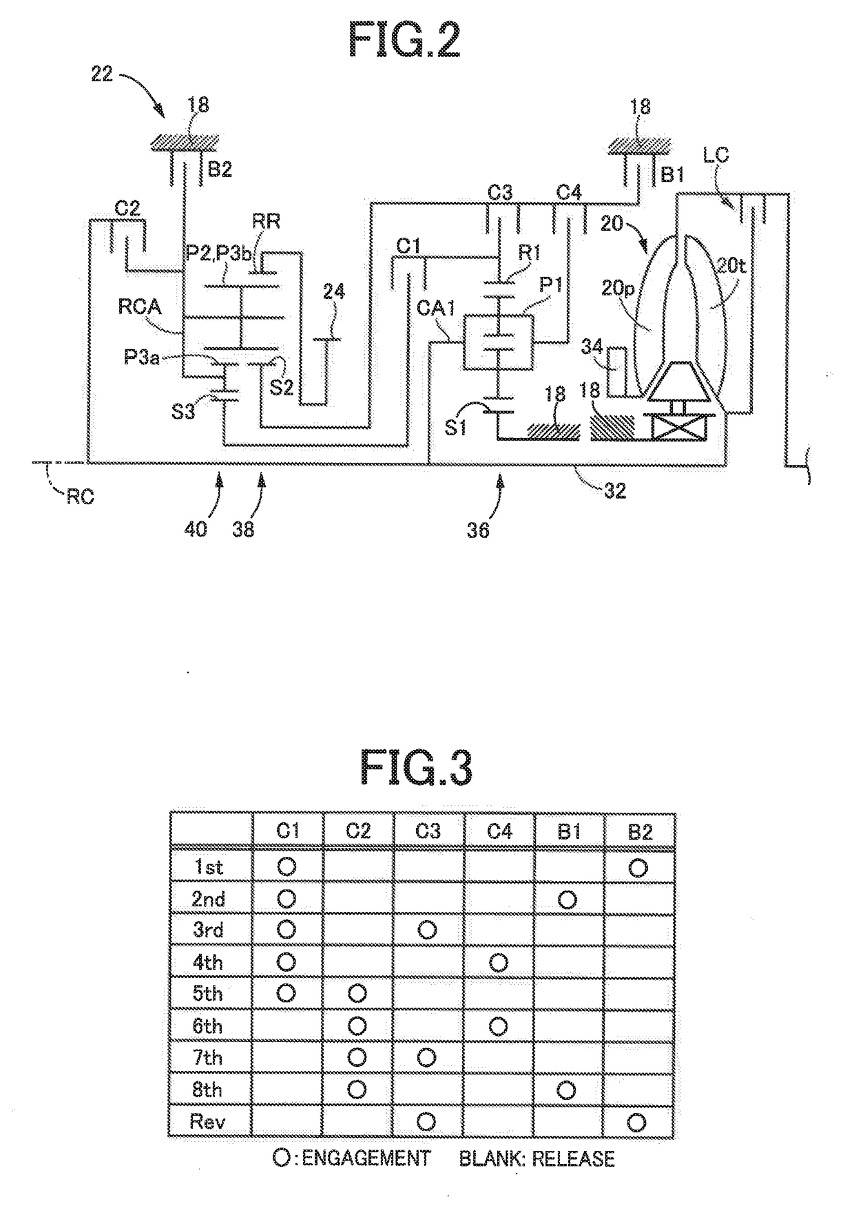
[0024]FIG. 1 is a diagram for explaining a general configuration of a vehicle 10 to which the present invention is applied and is a diagram for explaining main portions of a control system for various controls in the vehicle 10. In FIG. 1, the vehicle 10 includes an engine 12, drive wheels 14, and a vehicle power transmission device 16 (hereinafter referred to as a power transmission device 16) disposed in a power transmission path between the engine 12 and the drive wheels 14. The power transmission device 16 includes, in a case 18 acting as a non-rotating member attached to a vehicle body, a torque converter 20, an automatic transmission 22, a reduction gear mechanism 26 coupled to a transmission output gear 24 that is an output rotating member of the automatic transmission 22, a differential gear (differential gear device) 28 coupled to the reduction gear mechanism 26, etc. The power transmission device 16 also includes a pair of drive shafts (axles) 30 etc. coupled to the differ...


PUM


Abstract

A control device of a vehicle including a multi-speed transmission having plurality of gear positions different in gear ratio selectively established by controlling engagement and release predetermined engagement devices out of plurality engagement devices, the control device involves: shift control portion configured to provide delay control of delaying time point starting provision of release-side torque phase control reducing a torque capacity of release-side engagement device by a preset delay time with respect to time point of starting provision of a torque phase control of generating a torque capacity of an engagement-side engagement device during a torque phase in a drive upshift; and a delay time setting portion configured to preset the delay time such that the delay time is shortened when a shared torque of the release-side engagement device before start of the torque phase in the drive upshift is high, as compared to when the shared torque is low.

Description

INCORPORATION BY REFERENCE[0001]The disclosure of Japanese Patent Application No. 2016-144960 filed on Jul. 22, 2016 including the specification, drawings and abstract is incorporated herein by reference in its entirety.TECHNICAL FIELD[0002]The present invention relates to a control device of a vehicle including a multi-speed transmission having a plurality of gear positions different in gear ratio selectively established.BACKGROUND ART[0003]A control device of a vehicle is well known as a control device of a vehicle including a multi-speed transmission having a plurality of gear positions different in gear ratio selectively established by controlling engagement and release of predetermined engagement devices out of a plurality of engagement devices. For example, this corresponds to a vehicle control device described in Patent Document 1. In Patent Document 1, it is disclosed that, when gears are shifted in an automatic transmission where the gear shifting is achieved by switching e...

Claims


Application Information

Patent Timeline
IPC IPC(8): F16H61/02
CPCF16H61/0213F16H59/72F16H59/70F16H59/14F16H61/08F16H2061/0466
Inventor CHIMBE, TOMOHIROTSUKAMOTO, NORIHIROOTA, KEISUKEASAMI, TOMOHIROKAJIYAMA, YUJIFUKUDA, DAIKI
Owner TOYOTA JIDOSHA KK
Learn More