
Transmission Torque Converter Clutch Control

a technology of transmission torque converter and clutch, which is applied in the direction of rotary clutches, fluid couplings, gearings, etc., can solve the problems of fuel economy reduction, reduce the torque capacity of the clutch, reduce the magnitude of negative clutch slip, and increase the torque capacity

Active Publication Date: 2011-07-14
FORD GLOBAL TECH LLC
View PDF16 Cites 2 Cited by
  • Summary
  • Abstract
  • Description
  • Claims
  • Application Information

AI Technical Summary

Benefits of technology

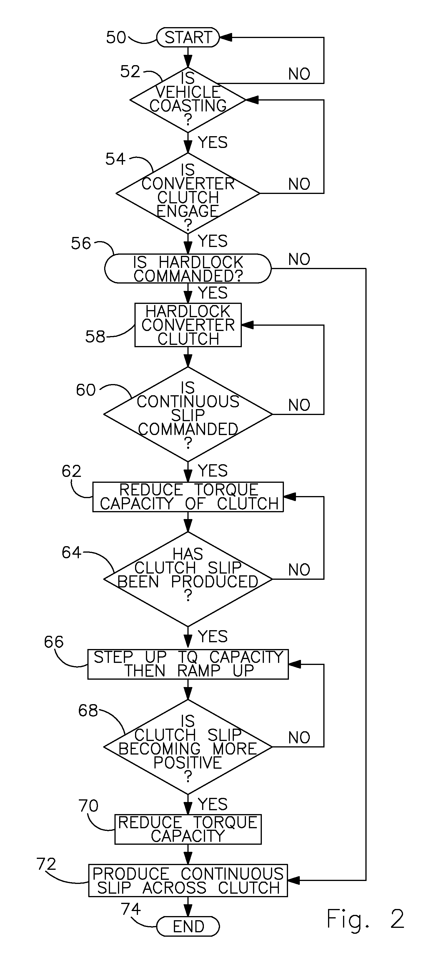
[0008]A method for controlling a vehicle torque converter lockup clutch during a deceleration coasting event includes producing slip across the clutch by reducing the clutch's torque capacity, decreasing the magnitude of negative clutch slip by increasing said torque capacity, and maintaining slip across the clutch.

Problems solved by technology

The method provides a consistent, acceptable control of the converter clutch during a deceleration coasting event without unlocking the torque converter, which produces a reduction in fuel economy.

Method used


Image

  • Transmission Torque Converter Clutch Control
  • Transmission Torque Converter Clutch Control
  • Transmission Torque Converter Clutch Control

Examples


Embodiment Construction

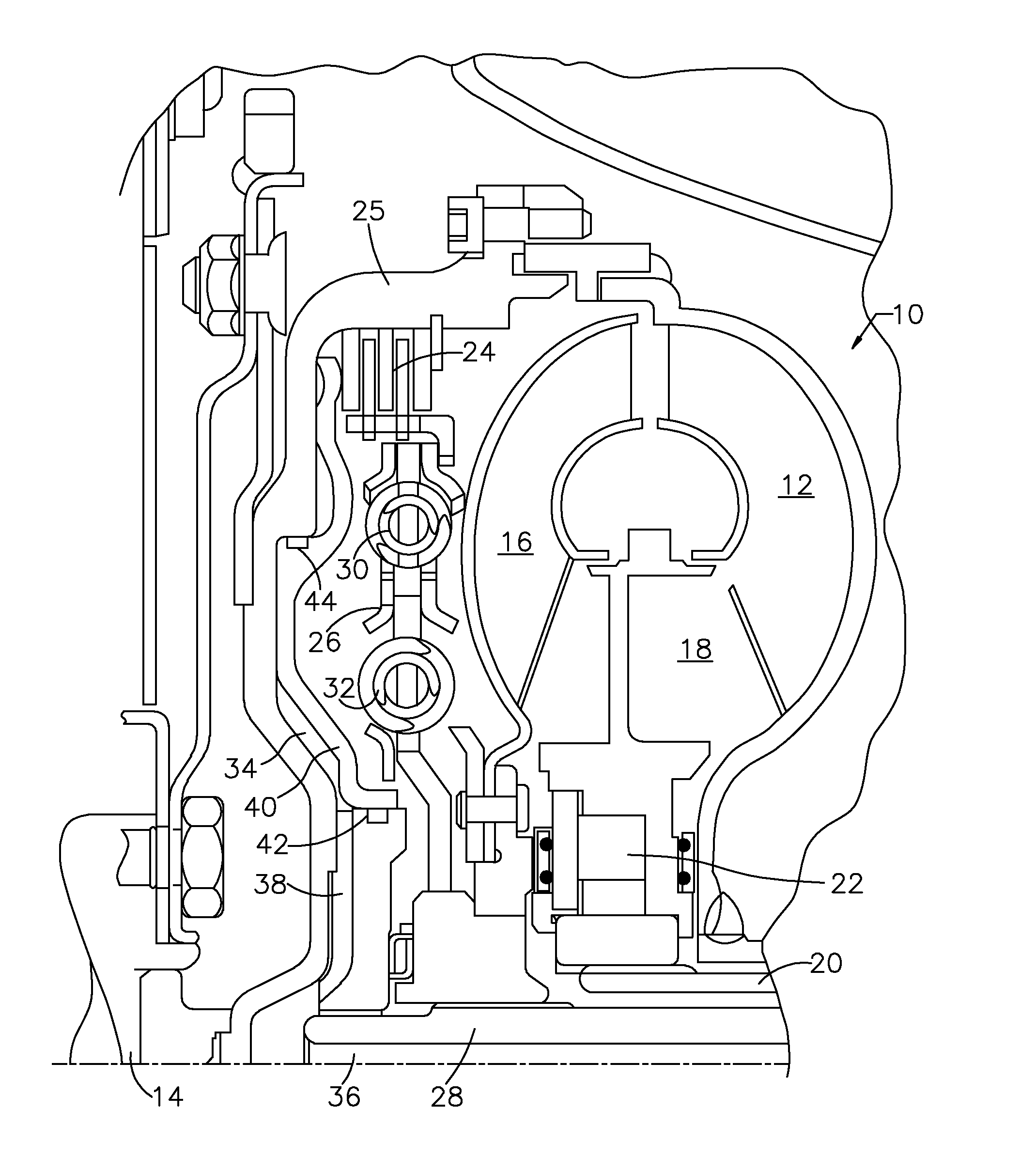
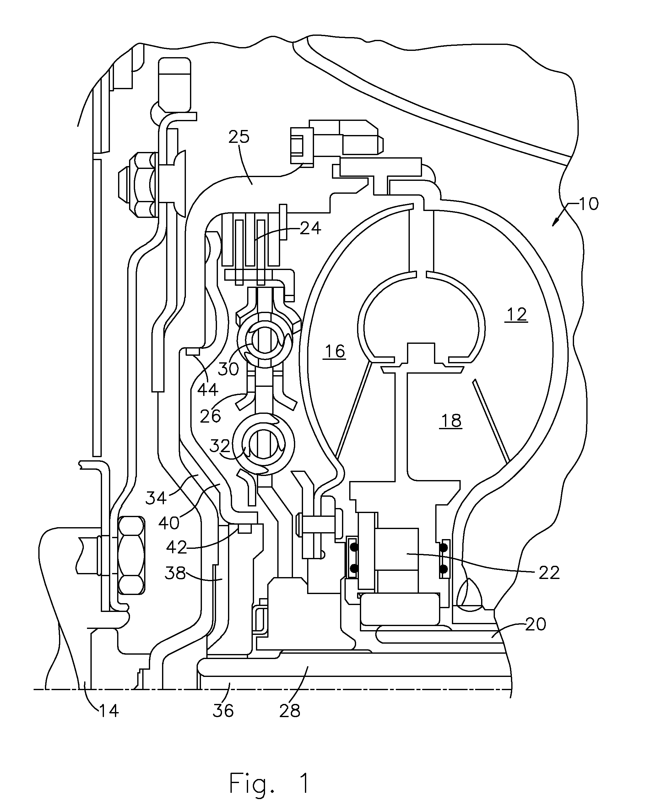
[0016]Referring first to FIG. 1, a torque converter 10 includes a bladed impeller wheel 12 connected to the crankshaft 14 of an internal combustion engine, a bladed turbine wheel 16, and a bladed stator wheel 18. The impeller, stator and turbine wheels define a toroidal fluid flow circuit, whereby the impeller is hydrokinetically connected to the turbine. The stator 18 is supported rotatably on a stationary stator sleeve shaft 20, and an overrunning brake 22 anchors the stator to shaft 20, thereby preventing rotation of the stator in a direction opposite the direction of rotation of the impeller, although free-wheeling motion in the opposite direction is permitted.

[0017]The torque converter assembly 10 includes a lockup clutch 24 located within a torque converter housing 25, which is secured to the impeller 12. The lockup clutch 24 alternately engages and disengages a drive connection between the housing 25 and a damper 26. The damper 26 is located in a torque path between clutch 24...


PUM


Abstract

A method for controlling a vehicle torque converter lockup clutch during a deceleration coasting event includes producing slip across the clutch by reducing the clutch's torque capacity, decreasing said slip by increasing said torque capacity, and maintaining slip across the clutch.

Description

BACKGROUND OF THE INVENTION[0001]1. Field of the Invention[0002]This invention relates generally to control of a motor vehicle torque converter clutch during negative torque coast downs to avoid lash and clunk.[0003]2. Description of the Prior Art[0004]During an aggressive deceleration fuel shutoff (ADFSO) coasting event of a vehicle equipped with an automatic transmission, when its torque converter clutch transitions from hard lock, i.e., with zero slip, to a controlled negative slip, preferably about negative 40 rpm, unlocking the converter clutch can cause fuel supply to the engine to resume. This is primarily due to a “stick-slip” phenomenon wherein the dynamic coefficient of friction of the clutch in its slipping state differs from the static coefficient of friction in its locked state.[0005]Due to the stick-slip occurrence, the torque transmitting capacity of the torque converter clutch must be substantially decreased to generate slip and then increased soon thereafter to main...

Claims


Application Information

Patent Timeline
Patent Type & Authority Applications(United States)
IPC IPC(8): F16H61/14F16H59/16
CPCF16H61/143Y10T477/73Y10T477/755F16H2061/145
Inventor RIES, SCOTT P.O'NEIL, BRIAN M.RIEDLE, BRADLEY D.
Owner FORD GLOBAL TECH LLC
Learn More