
Recoil reducer when shooting bullet from firearm
a reducer and reducer technology, applied in the direction of weapons, butts, weapon components, etc., can solve the problems of misalignment of sight, large impact of bullet shot, and heavy burden on the shooter, so as to reduce the load applied to the shooter
- Summary
- Abstract
- Description
- Claims
- Application Information
AI Technical Summary
Benefits of technology
Problems solved by technology
Method used
Image

Examples
Embodiment Construction
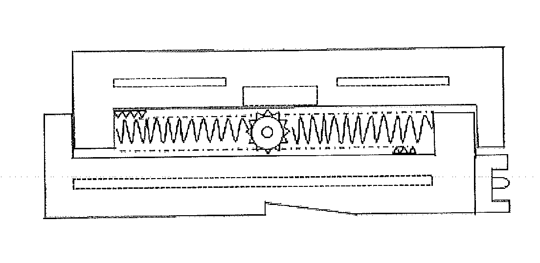
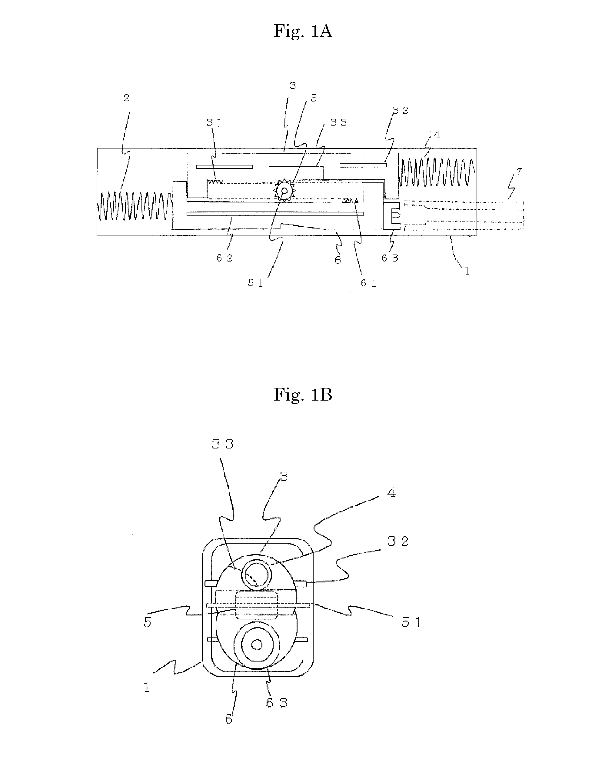
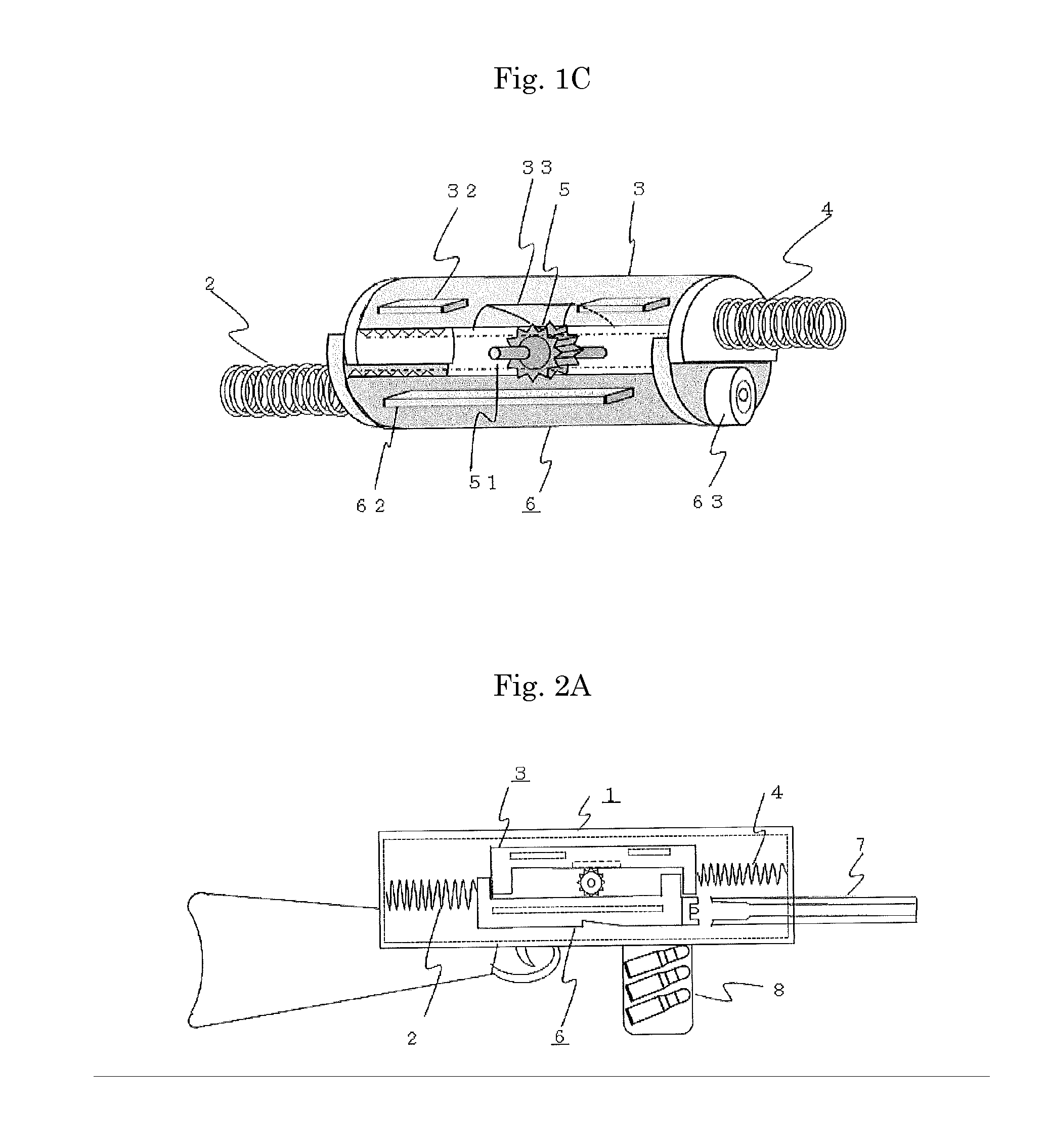
[0037]Hereafter, the present invention will be explained based on the drawings. FIG. 1A shows a recoil reducer concerning an embodiment of the present invention. As shown in FIG. 1, a member 3 (hereafter, referred to as a forward moving member) is included in a casing 1 of a machine part so that the forward moving member 3 is slidably movable in an opposite direction with respect to a bolt 6. The forward moving member 3 has a substantially semicylindrical shape as shown in FIG. 1B and 1C. Movement restriction projections having a semicircular shape and projected downward are formed on both ends of the forward moving member 3. Thus, the forward moving member 3 has a U-shape as a whole when viewed from the side. The forward moving member 3 is installed on a slit groove (second slit groove) of the casing of the machine part by a protruding slit 32 so that the forward moving member 3 is slidably movable. The forward moving member 3 is in contact with a return spring 4 (second elastic bo...
PUM
 Abstract
Description
Claims
Application Information