Ball screw mechanism

a technology of ball screw and screw body, which is applied in the direction of gearing, gearing elements, hoisting equipment, etc., can solve the problems of increased manufacturing cost, difficulty in machined nut, and deterioration of assemblability, so as to prevent operation failure and noise, increase manufacturing cost, and facilitate assembly

Inactive Publication Date: 2006-07-20
NSK LTD
View PDF1 Cites 8 Cited by
  • Summary
  • Abstract
  • Description
  • Claims
  • Application Information

AI Technical Summary

Benefits of technology

[0011] The invention is made in consideration of the above-mentioned problems, and it is an advantage of the invention to provide a ball screw mechanism capable of securing reliability regardless of use conditions.
[0012] The invention is made in consideration of the above-mentioned problems, and it is an advantage of the invention to provide a ball screw mechanism capable of restraining the operation fail and the noise from occurring without an increase of the manufacturing cost.
[0014] The invention is made in consideration of the above-mentioned problems, and it is an advantage of the invention to provide a ball screw mechanism capable of firmly fixing a circulating member to a nut.
[0015] According to a first aspect of the invention, a ball screw mechanism includes a housing that has a recess; a screw shaft that have a male thread groove on an outer peripheral surface thereof; a nut that is disposed so as to surround the screw shaft, has a female thread groove on an inner peripheral surface thereof, and has a cylindrical hole on an outer peripheral surface thereof; a plurality of balls that is disposed so as to roll along a raceway formed between the thread grooves facing each other; a circulating member that is mounted to the nut so as to return the balls from one end of the raceway to the other end thereof; and a mounting member that fixes the circulating member to the nut. In this case, the mounting member has a cylindrical surface to be engaged with the cylindrical hole, and extends outward in a radial direction of the nut and can be engaged with the recess of the housing in a state in which the mounting member is assembled with the nut.
[0016] According to the ball screw mechanism of a first aspect of the invention, since the mounting member has a cylindrical surface to be engaged with the cylindrical hole, it is possible to position a mounting member and a nut by only engaging the cylindrical surface with the cylindrical hole. Accordingly, it is possible to easily perform an assembly. In addition, when a force is applied to the mounting member from the housing in the rotational direction of the nut, the force is partially applied to the cylindrical hole. Therefore, it is possible to reduce a load applied to screws that fix the mounting member. Furthermore, since the mounting member extends outward in a radial direction of the nut and can be engaged with the recess of the housing in a state in which the mounting member is assembled with the nut, it is possible to prevent the nut from being rotated with respect to the housing, and it is not necessary to provide a snap ring, thereby providing a ball screw mechanism having simple structure. Moreover, if the ‘cylindrical hole’ is not completely cylindrical and has at least one part of a cylindrical surface, it is sufficient.
[0017] In addition, after the cylindrical surface is engaged with the cylindrical hole, it is necessary to align the assembly positions of the mounting member and the circulating member. However, when the mounting member is engaged with the cylindrical hole, if a structure for aligning the assembly positions is provided, it is possible to automatically align the assembly positions, whereby assemblability is improved.

Problems solved by technology

However, when the nut is provided with the protrusion, there has been a problem in that it is difficult to machine the nut and thus the manufacturing cost thereof is increased.
Furthermore, there is a problem that it is difficult to find thread holes to fasten bolts, whereby assemblability deteriorates.
For this reason, there is a problem that the structure is to be large.
If a gap between the tube retainer and the groove is small, there is a possibility that the operation fail occurs due to the interference between the tube retainer and the housing.
For this reason, there is a possibility that a noise occurs.
However, when the accuracy of the parts is improved to manage the gap between the tube retainer and the groove in an optimum range, there is a problem that manufacturing cost is caused to be increased.
Still further, in the related art disclosed in Patent Document 1, since the tube retainer is mounted to the nut using screws, if assembly accuracy is bad, there is a possibility that the operation fail occurs due to the interference between the tube retainer and the housing.
Furthermore, when the tube retainer is made of resin to reduce the weight thereof, there is a possibility that the life span of the ball screw mechanism deteriorates depending on use conditions due to the fact that heat resistance of a resin is inferior to that of a metal.
As a result, a problem may occur in that the screws are loosened.
However, a new problem may occur in that labor hour required for coating the locking agent increases or disassembly of the tube retainer during maintenance becomes difficult.
However, in Patent Document 2, the end caps are made of synthetic resin, such as plastics, which may cause deformation or destruction due to a fastening force of the screws or a temperature change.

Method used


Image

  • Ball screw mechanism
  • Ball screw mechanism
  • Ball screw mechanism

Examples


first embodiment

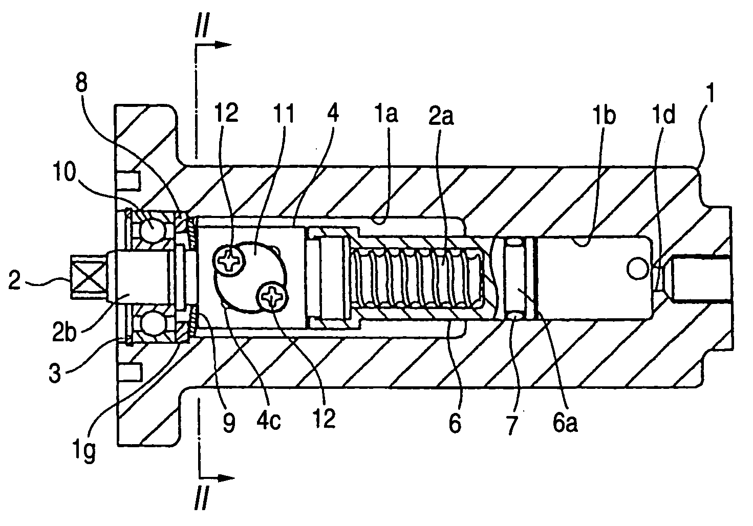
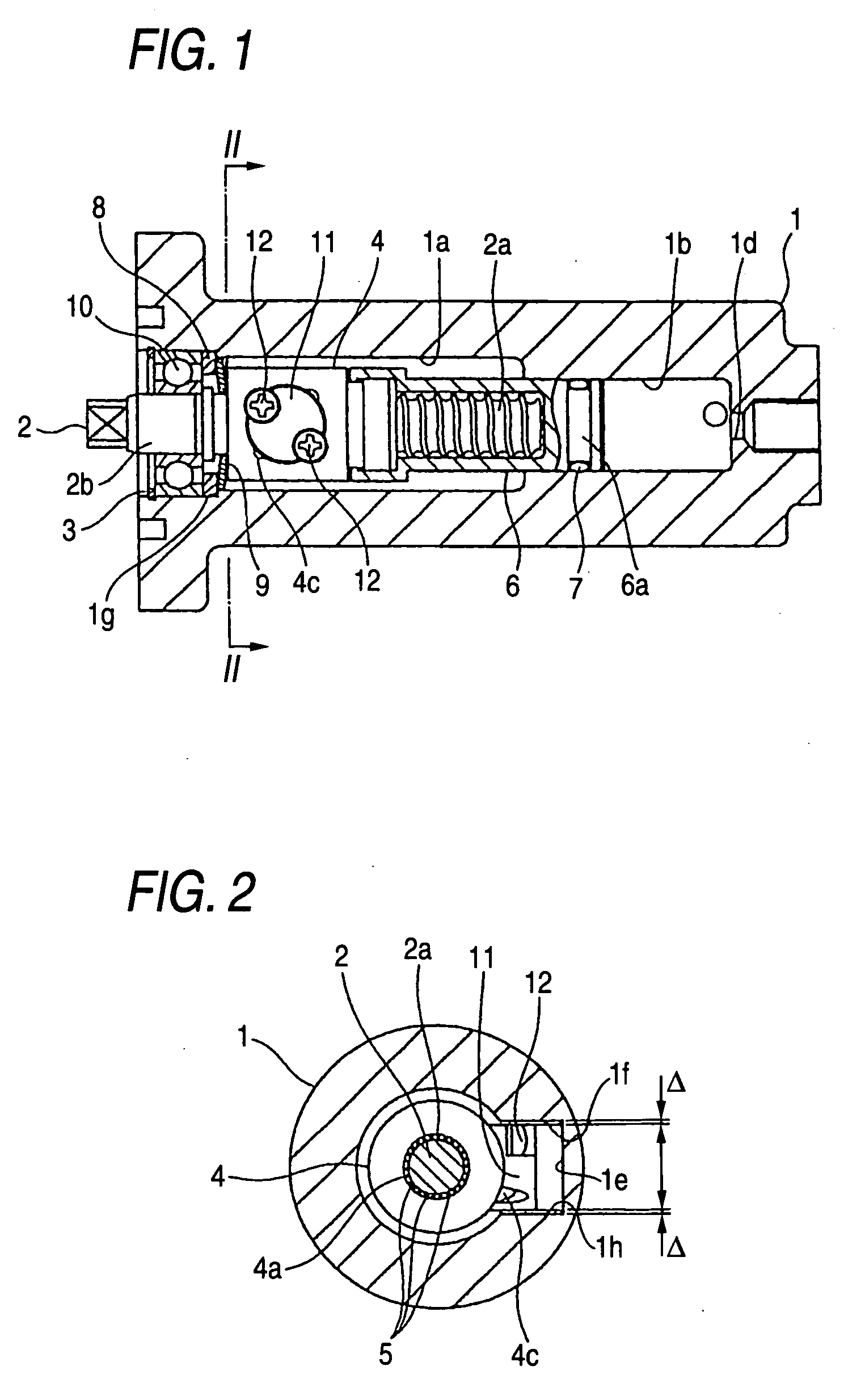
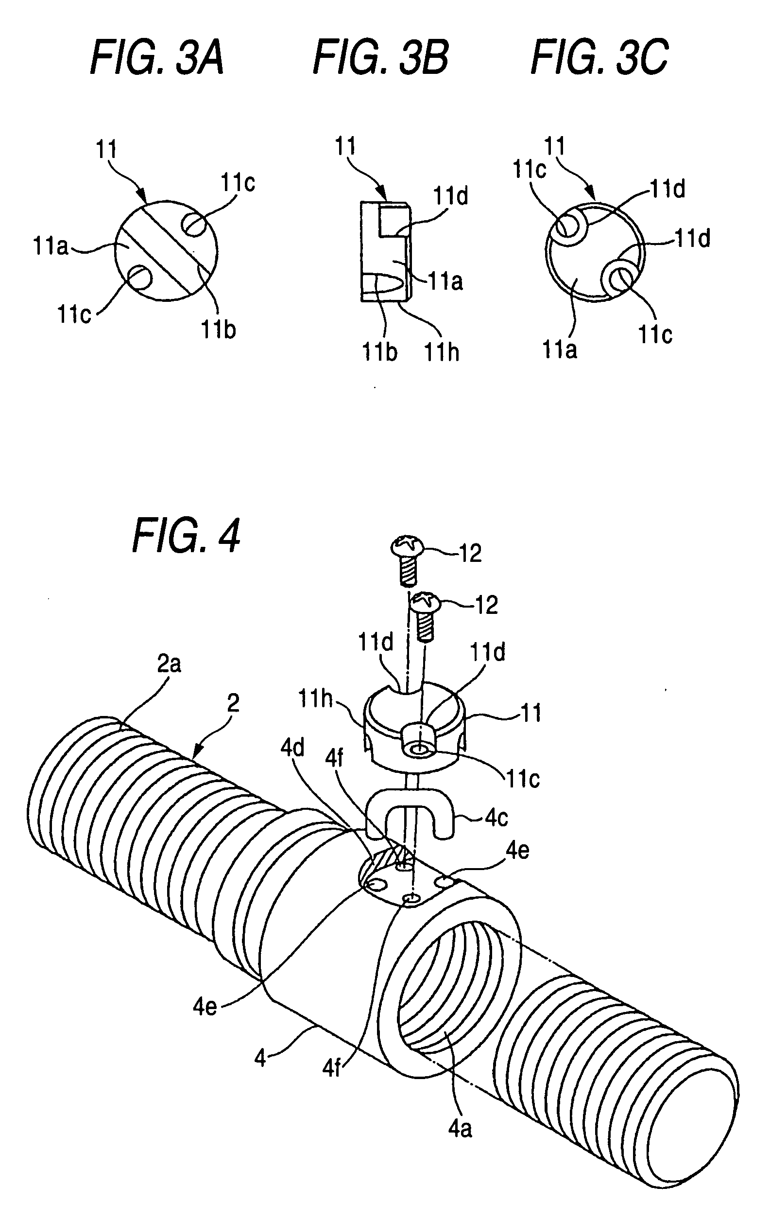
[0066] Hereinafter, a preferred embodiment of the invention will be described with reference to accompanying drawings. FIG. 1 is a cross-sectional view showing a cylinder device in which a ball screw mechanism of a first embodiment is assembled. FIG. 2 is a cross-sectional view taken along line II-II of FIG. 1 as seen in a direction indicated by arrows. FIG. 3A is a bottom view of a mounting member, FIG. 3B is a side view thereof, and FIG. 3C is a top view thereof. FIG. 4 is a perspective view showing a state in which a tube and a mounting member are exploded from the nut.

[0067] In the cylinder device shown in FIG. 1, a cylindrical case 1 (also called as a housing) has a cavity 1a for receiving a ball screw mechanism in the inside thereof, a cylinder portion 1b having a constant diameter, a fluid inlet 1c (FIGS. 5 and 6) communicating with the cylinder portion 1b, and a fluid outlet 1d. In addition, the fluid inlet 1c may be provided with a check valve for allowing only an inflow o...

second embodiment

[0081] Hereinafter, a preferred embodiment of the invention will be described with reference to accompanying drawings. FIG. 7 is a cross-sectional view showing a cylinder device in which a ball screw mechanism of a second embodiment is assembled. FIG. 8 is a cross-sectional view taken along line II-II of FIG. 7 as seen in a direction indicated by arrows. FIG. 9 is cross-sectional view taken along line III-III of FIG. 7 as seen in a direction indicated by arrows. FIG. 10 is a top view showing a mounting member in a mounting state.

[0082] In the cylinder device shown in FIG. 7, a cylindrical case 101 (also called as a housing) has a cavity 101a for receiving a ball screw mechanism in the inside thereof, a cylinder portion 101b having a constant diameter, a fluid inlet 101c (FIGS. 11 and 12) communicating with the cylinder portion 101b, and a fluid outlet 101d. In addition, the fluid inlet 101c may be provided with a check valve for allowing only an inflow of the fluid, and the fluid o...

third embodiment

[0097] Hereinafter, a preferred embodiment of the invention will be described with reference to accompanying drawings. FIG. 13 is a cross-sectional view showing a cylinder device in which a ball screw mechanism of a third embodiment is assembled. FIG. 14 is a cross-sectional view taken along line II-II of FIG. 13 as seen in a direction indicated by arrows. FIG. 15 is a view illustrating the operation of the cylinder device. The cylinder device can be used to push brake fluid at the time of braking of a vehicle.

[0098] In the cylinder device shown in FIG. 13, a cylindrical case 201 (also called as a housing) has a cavity 201a for receiving a ball screw mechanism in the inside thereof, a cylinder portion 201b having a constant diameter, a fluid inlet 201c (FIG. 15) communicating with the cylinder portion 201b, and a fluid outlet 201d. In addition, the fluid inlet 201c may be provided with a check valve for allowing only an inflow of the fluid, and the fluid outlet 201d may be provided...


PUM


Abstract

Since a mounting member 11 has a cylindrical surface 11h to be engaged with a cylindrical hole 4d, it is possible to position a mounting member 11 and a nut 4 by only engaging the cylindrical surface 11h with the cylindrical hole 4d. Accordingly, it is possible to easily perform an assembly. In addition, when a force is applied to the mounting member 11 from the guide groove 1e of the case 1 in the rotational direction of the nut 4, the force is partially applied to the cylindrical hole 4d. Therefore, it is possible to reduce a load applied to screws 12 that fix the mounting member 11, and to use thinner screws.

Description

[0001] The present application claims foreign priority under 35 USC 119 based on Japanese Patent Application Nos. 2005-225192 filed on Aug. 03, 2005, 2005-181370 filed on Jun. 22, 2005, 2005-045396 filed on Feb. 22, 2005, 2005-043384 filed on Feb. 21, 2005, 2005-043383 filed on Feb. 21, 2005 and 2004-361334 filed on Dec. 14, 2004, the contents of which are incorporated herein by reference in their entirety, and concurrently with the filing of this U.S. patent application. BACKGROUND OF THE INVENTION [0002] The present invention relates to a ball screw mechanism that is assembled to general industrial machinery or is used for automobiles. [0003] Recently, as labor saving is progressed in the automobile industry, a system that operates a transmission or a parking brake of the automobile by means of the force of the electrical motor instead of manually operating it. The electrical actuator to be used as described above uses a ball screw mechanism in order to efficiently convert the rot...

Claims


Application Information

Patent Timeline
Patent Type & Authority Applications(United States)
IPC IPC(8): F16H25/22
CPCY10T74/19767F16H25/2214
Inventor YAMASHITA, TOMOFUMIKAWADA, DAISAKUSAITOU, SHINGONAWAMOTO, TAIKOU
Owner NSK LTD
Why Eureka
Try Eureka