Radio communication device, radio communication method, and radio communication program

a radio communication and radio communication technology, applied in the field of radio communication devices, radio communication methods and radio communication programs, can solve the problems of affecting the reception or transmission of data signals in other radio communication systems, and reducing the utility efficiency of a shared frequency band. , to achieve the effect of reliable radio communication

Inactive Publication Date: 2007-08-09
KK TOSHIBA
View PDF24 Cites 56 Cited by
  • Summary
  • Abstract
  • Description
  • Claims
  • Application Information

AI Technical Summary

Benefits of technology

[0010]The present invention has been contemplated in order to overcomes problems of the related art, and is intended to provide a radio communication device, a radio communication method and a radio communication program, all of which assure reliable radio communications between a plurality of radio communications systems sharing the same frequency channel, and protect the radio communication system against interferences between them.

Problems solved by technology

Therefore, the base station may adversely affect the reception or transmission of the data signal in other radio communication systems.
Further, since the dummy signal is allocated to the interregnum of the data signal transmission-reception frame, no data signals can be transmitted in other radio communication systems.
This will lead to reduced utility efficiency of a shared frequency band.

Method used


Image

  • Radio communication device, radio communication method, and radio communication program
  • Radio communication device, radio communication method, and radio communication program
  • Radio communication device, radio communication method, and radio communication program

Examples


first embodiment

[Outline of Communication System]

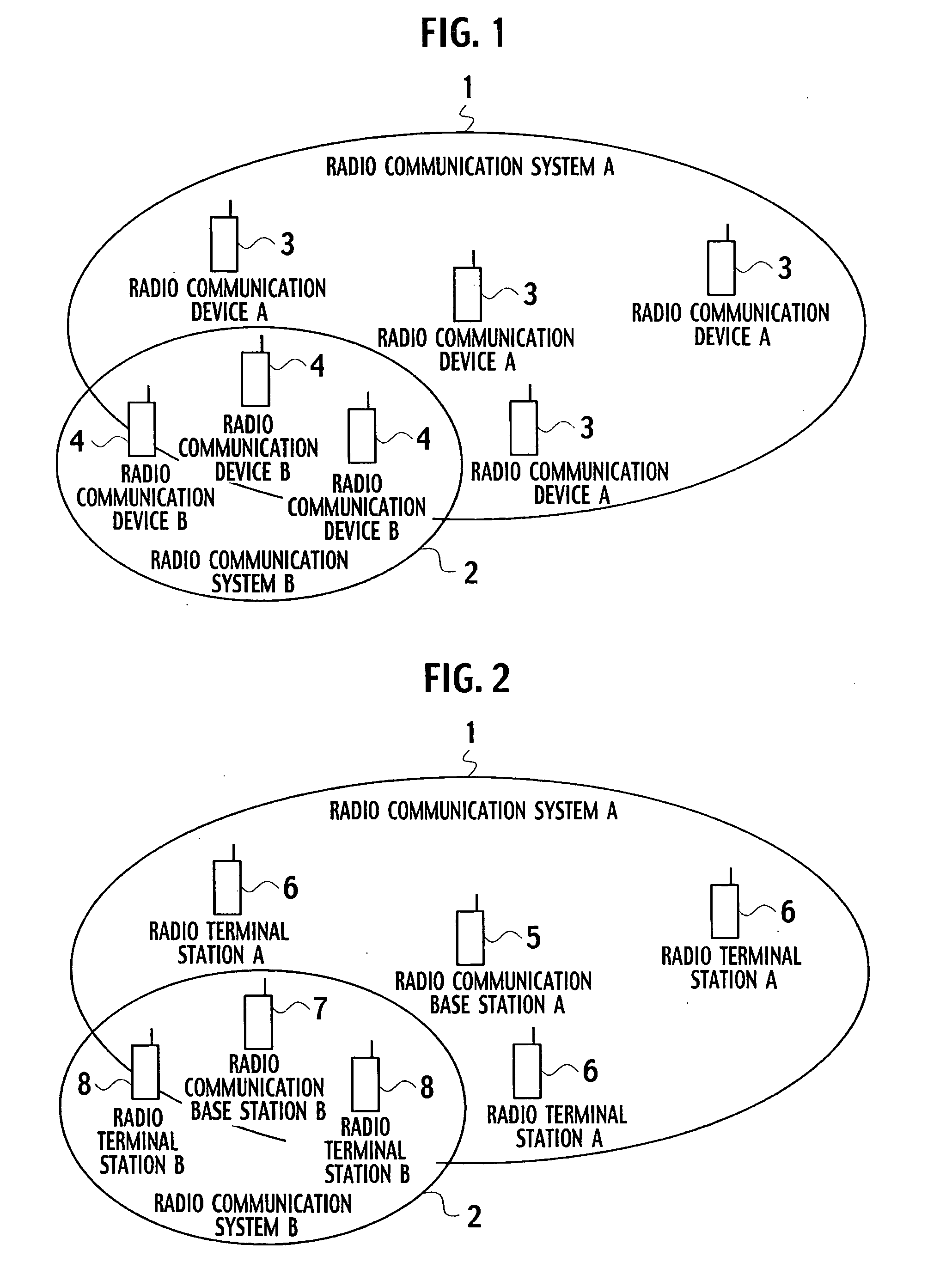
[0091]FIG. 1 schematically shows an example of a configuration of a radio communication system 2 (second radio communication system B), which is constituted by a plurality of communication devices 4 (radio communication devices B). The radio communication system and radio communication device will be called the “communication system”, and “communication device” hereinafter.) The communication system 2 shares a frequency band with a communication system 1 (first communication system A) constituted by a plurality of communication devices 3 (or A).

[0092]The communication system 1 operates on the W-CDMA (wide band division multiple access), PDC (personal digital cellular), GSM (global system for mobile radio communication), MAN (metropolitan area network) such as IEEE802.16e, or LAN such as IEEE802.11. At present, the communication system 2 does not operate on a standard system, which will be specified to be the standard system in future. The communicati...

second embodiment

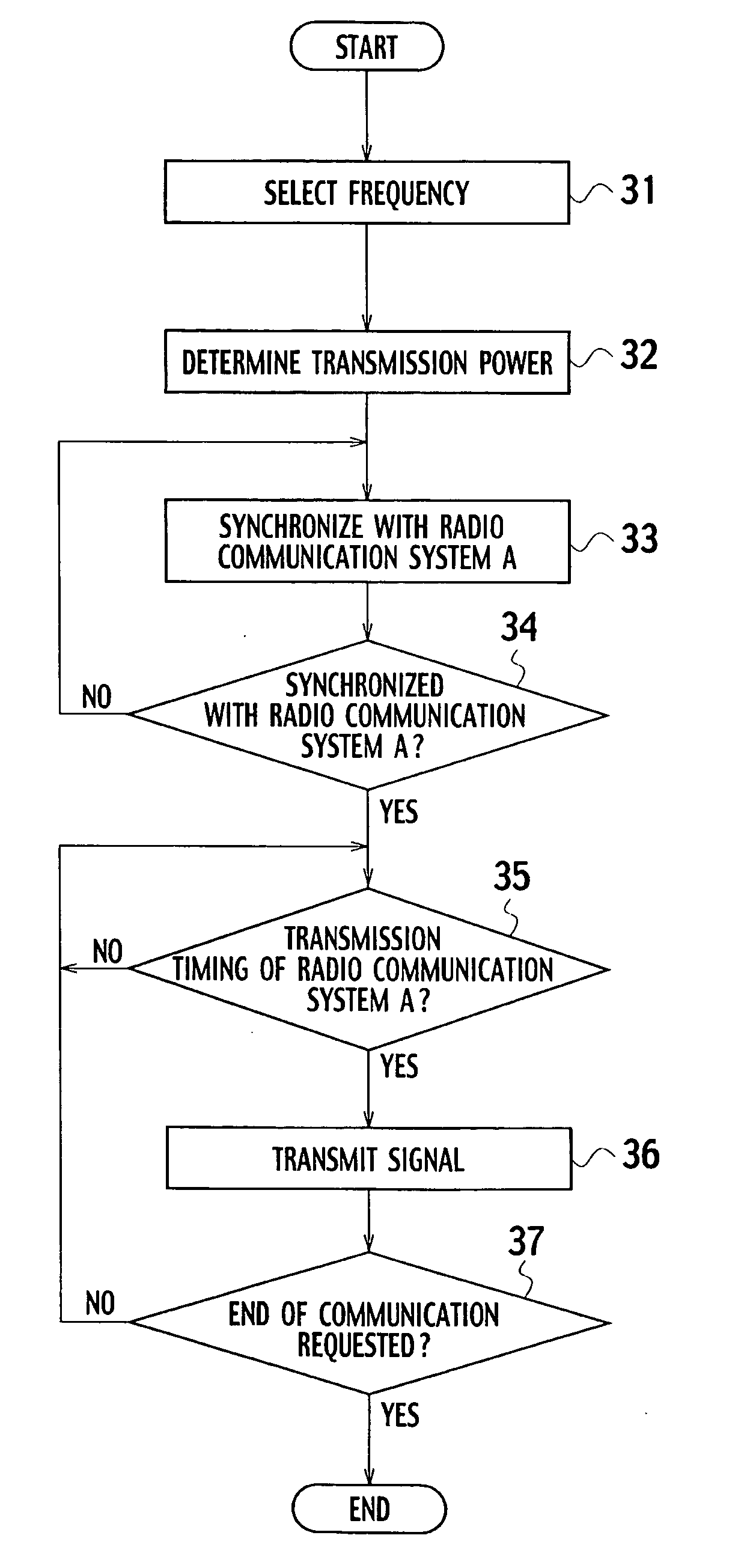
[0108]A second embodiment relates to modified modifications of the first embodiment. The operations are executed in accordance with the flowchart in FIG. 7.

[0109]With the communication device 4 shown in FIG. 4, the control unit 25 selects a frequency at which the communication device 4 operates (step 31), and notifies the selected frequency to the synchronizer 23 and the transmitter-receiver unit 24. The transmission power determining unit 26 determines transmission power which enables radio communication with other communication devices 4 of the communication system 2. The transmission power is determined such that reception power of a signal is equal to or smaller than a predetermined threshold (step 51). The predetermined threshold denotes a value equivalent to a noise level or the like, and does not affect the signal transmission and reception of the base station 5 (see FIG. 2). The transmission power determining unit 26 selects transmission power, and outputs it to the control ...

third embodiment

[0117]A third embodiment of the invention relates to a modification of the first embodiment.

[Configuration of Communication Device]

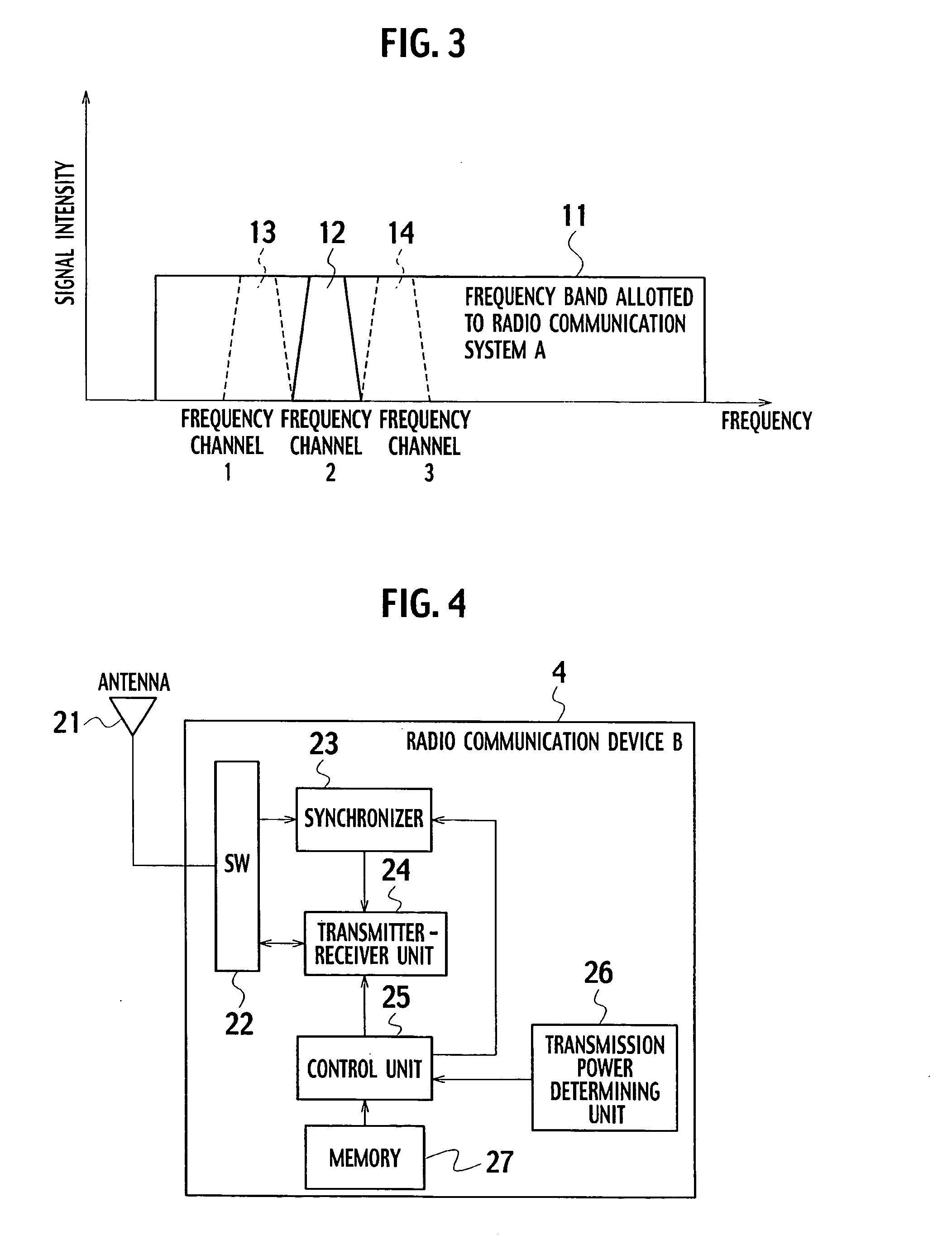
[0118]In this embodiment, each communication device 4 constituting the communication system 2 includes a carrier sensor 111, as shown in FIG. 11.

[Operation of Communication System and Radio Communication Device]

[0119]Referring to FIG. 12, the control unit 25 of the communication device 4 selects a frequency for the operation of the communication device 4 (step 31), and outputs the selected frequency to the synchronizer 23, the transmitter-receiver section 24 and the carrier sensor 111. The transmission power determining unit 26 determines signal transmission power so that radio communications can be established between communication devices 4 of the communication system 2, and so that reception power of the base station 5 of the communication system 1 is smaller than a predetermined threshold (step 51). The predetermined threshold has a level equivalent ...


PUM


Abstract

A terminal station radio communication device belongs to a second radio communication system which shares a frequency channel with a first radio communication system in which a radio terminal station communicates with a radio base station in a predetermined time period using a predetermined frequency channel. The terminal station radio communication device includes: a transmission power determining unit which sets up signal transmission power, the signal transmission power being usable for communications between radio communication devices belonging to the second radio communication system, and being determined such that reception power at the radio base station is below a predetermined threshold; a synchronizer enabling the radio terminal station to obtain timing information to start signal transmission; and a signal transmitter starting transmitting the signal at the timing represented by the timing information and terminating the signal transmission within a predetermined time period.

Description

CROSS REFERENCE TO RELATED APPLICATION[0001]This application is based upon and claims the benefit of priority from the prior Japanese Patent Application No. 2006-031733 filed on Feb. 8, 2006, the entire contents of which are incorporated herein by reference.BACKGROUND OF THE INVENTION[0002]1. Field of the Invention[0003]This invention relates to a radio communication device, a radio communication method and a radio communication program, and more particularly relates to radio communication devices which share a particular frequency band and constitute a plurality of radio communication systems, a radio communication method which controls operations of the radio communication systems, and a radio communication program which is applied to execute the foregoing method.[0004]2. Description of the Related Art[0005]There are communication devices which share a particular frequency band in a radio communication system, and a radio communication method which controls operations of the radio...

Claims


Application Information

Patent Timeline
Patent Type & Authority Applications(United States)
IPC IPC(8): H04J3/06H04W16/14H04W52/24
CPCH04W52/245H04W16/14H04W74/0808
Inventor TANDAI, TOMOYADEGUCHI, NORITAKAHORIGUCHI, TOMOYATOMIOKA, TAZUKOTOMIZAWA, TAKESHI
Owner KK TOSHIBA
Why Eureka
Try Eureka