Fixing device and image forming apparatus using the same

Inactive Publication Date: 2007-03-01
RICOH KK
View PDF9 Cites 8 Cited by
  • Summary
  • Abstract
  • Description
  • Claims
  • Application Information

AI Technical Summary

Benefits of technology

[0021] According to the above-aspects, since a ratio of a radius of curvature of a pressure applying member with an elastic layer in the transferring direction to a radius of curvature of an outer diameter of a heating roller is set to 1.1 or more, an image fix

Problems solved by technology

However, the measure to apply such energy by increasing a heat value of the heater goes against the energy saving.
However, an increase in diameter of the roller goes against a downsizing of the housing.
As a result, a printing time is also prolonged.
Also, there is the method of maintaining a temperature of the heating roller by supplying a heat as needed during the print standby, but such method is contrary to the energy saving.
In some cases the fixing performance of the toner becomes uneven.
In addition, it is possible that an uneven pressure distribution causes a paper

Method used


Image

  • Fixing device and image forming apparatus using the same
  • Fixing device and image forming apparatus using the same
  • Fixing device and image forming apparatus using the same

Examples


embodiment 1

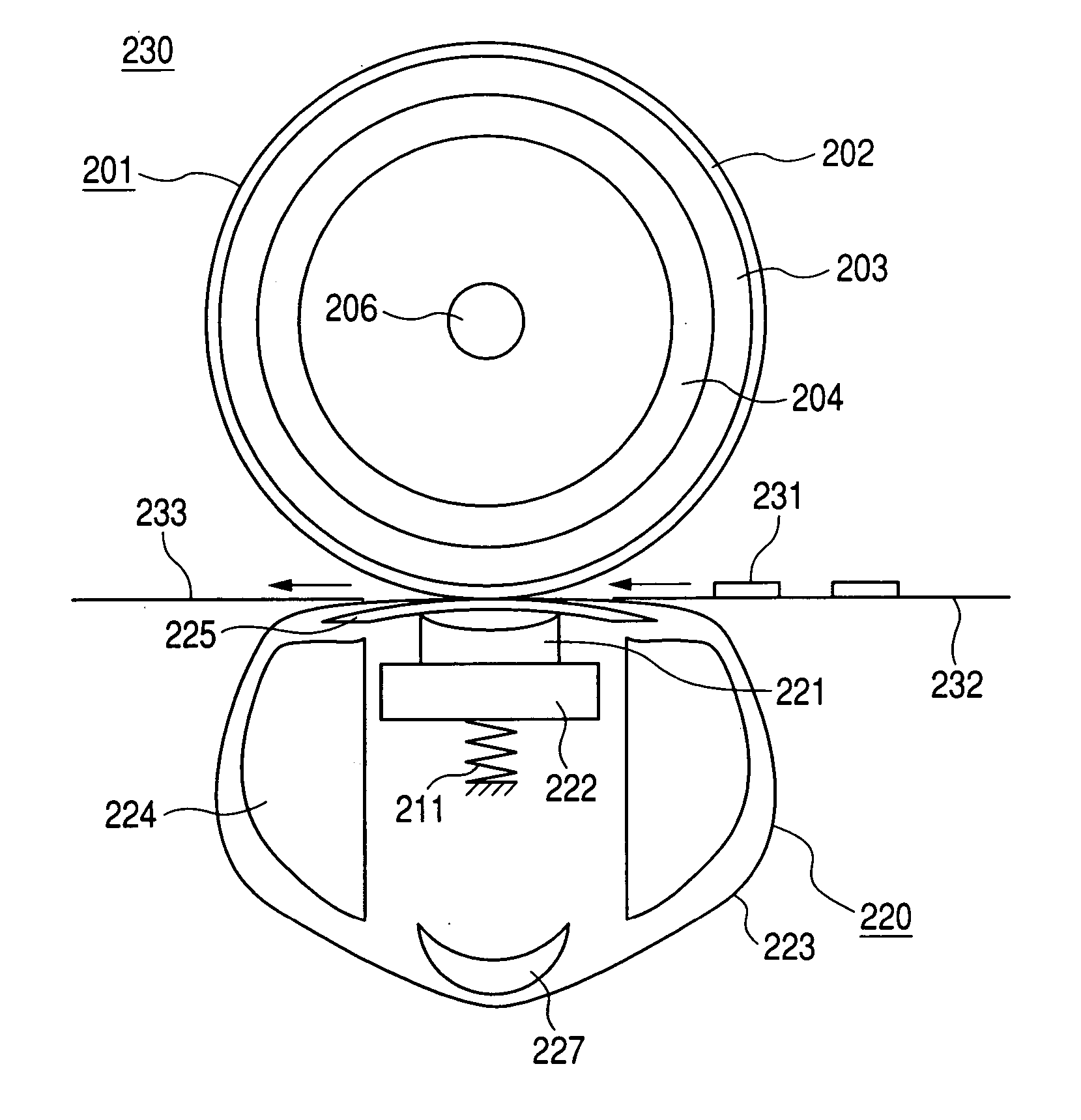
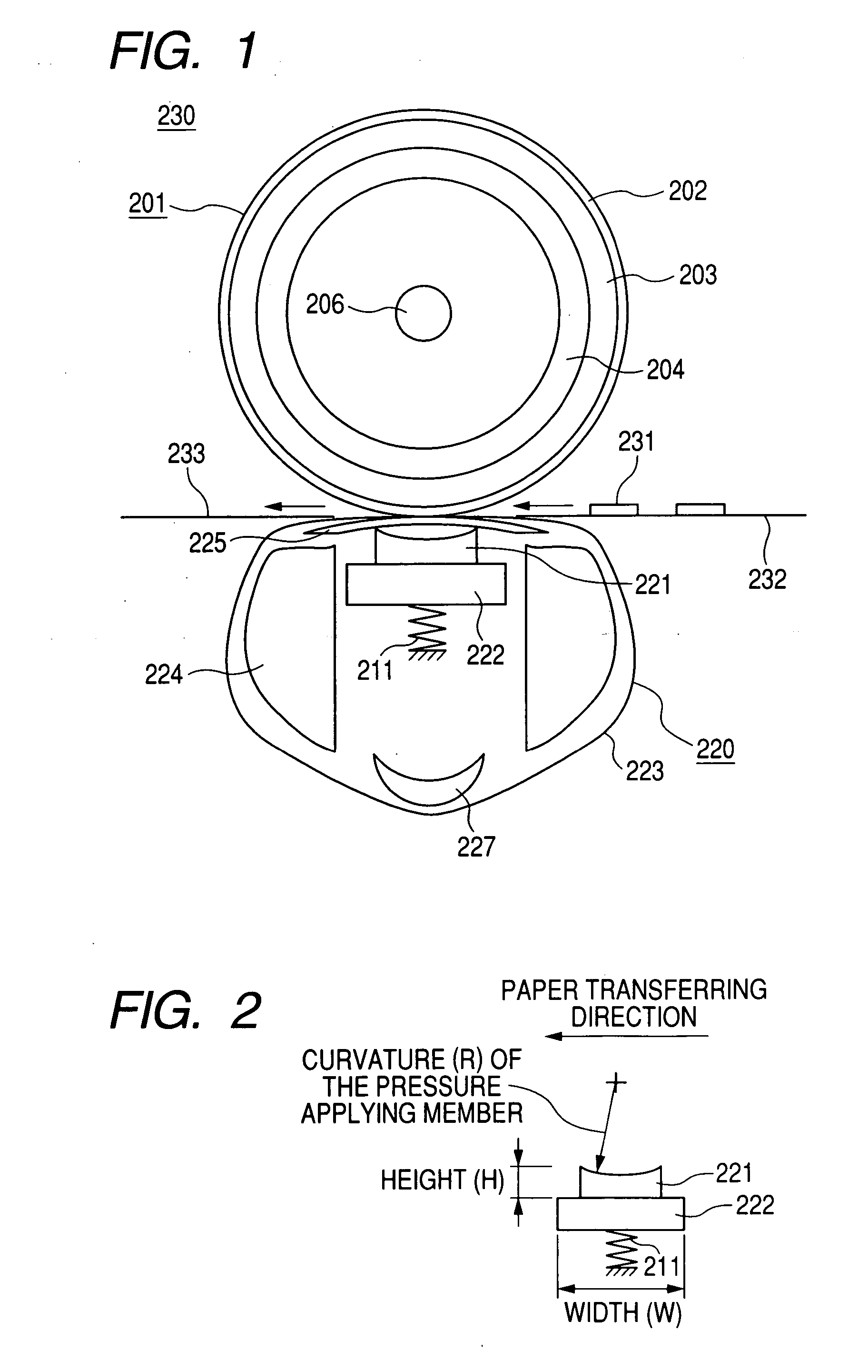
[0034] An image forming apparatus according to a first embodiment will be explained with reference to FIGS. 1 to 3 hereinafter. FIG. 1 is an exemplary schematic view showing a fixing device according to a first embodiment of the invention.

[0035] In FIG. 1, a fixing device 230 is composed of a heating / fixing roller 201 and a pressurizing / fixing mechanism portion 220, which are arranged such that a recording medium 232 on which an unfixed toner 231 is put can be passed through them.

[0036] The heating / fixing roller 201 for heating the unfixed toner has a heat-resistant resin layer 202 made of fluororesin, PFA, or the like on a surface coating portion. The heating / fixing roller 201 has an elastic layer 203 made of silicon rubber, fluorine-containing rubber, or the like on its inner side, and has further a core layer 204 on its inner side. Also, a heat source 206 is provided to the inside of a core layer of the heating / fixing roller 201.

[0037] The pressurizing / fixing mechanism portion...

embodiment 2

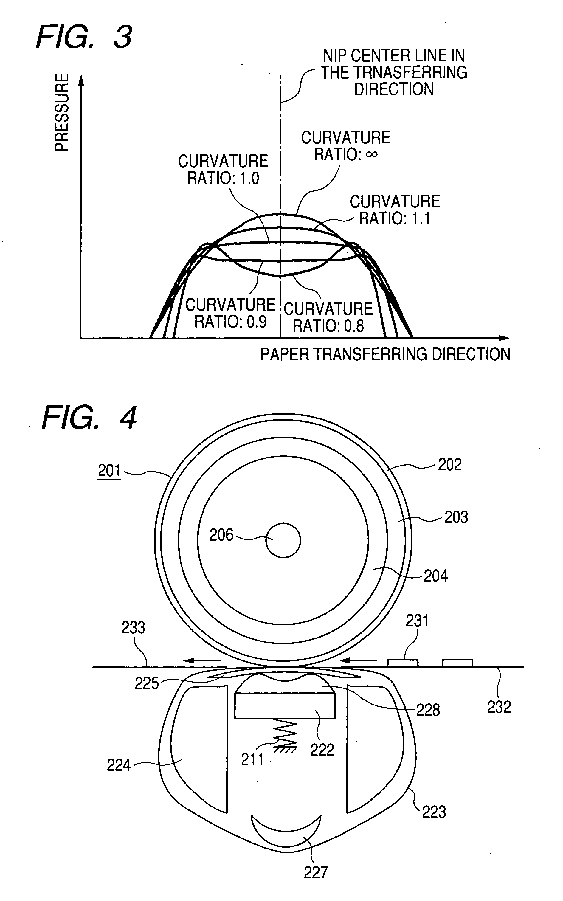
[0054] A configuration in which the pressure applying member 221 set forth in the embodiment 1 is varied will be explained with reference to FIG. 4 hereunder.

[0055] Since the configuration except the pressure applying member 221 is similar to that in the embodiment 1, their explanation will be omitted herein.

[0056] A non-image surface side curved end unfolded-fan-type pressure applying member 228 is employed in place of the pressure applying member 221 in the embodiment 1. In the non-image surface side curved end unfolded-fan-type pressure applying member 228, a curvature is provided in the transferring direction and also both end portions in the transferring direction are shaped into a shape of an unfolded fan to prevent the deformation in the turning direction when the heating roller is rotated.

[0057] A sectional shape of the pressure applying member 221 has the shape of the unfolded fan a width of which in the transferring direction is increased gradually from the side opposin...

embodiment 3

[0068] An image forming apparatus according to a third embodiment of the present invention will be explained based on a color laser printer shown in FIG. 6 to FIG. 8 hereinafter.

[0069] A color laser printer 301 is roughly constructed by an endless photosensitive belt 302 as a photosensitive body, an intermediate transfer member 303 arranged in a position at which this member contacts the photosensitive belt 302, and a belt nip system fixing device 314.

[0070] The photosensitive belt 302 is wound on a driving roller R2 and an idler roller R1, which also acts as a tension roller to apply a tensile force, to extend vertically and is driven at a predetermined speed in an arrow a direction. Also, an outer peripheral surface of the photosensitive belt 302 is charged uniformly by a charger 304 that is arranged in close vicinity of this belt. The charged photosensitive belt 302 is exposed by an exposure unit 305, and an electrostatic latent image is formed on a surface of the belt. Four de...


PUM


Abstract

A ratio of a radius of curvature of a pressure applying member with an elastic layer, which pushes an endless belt wound around an endless heating member with pressure, in a transferring direction to a radius of curvature of an outer diameter of the heating roller is set to 1.1 or more.

Description

BACKGROUND [0001] 1. Technical Field [0002] The present invention relates to a fixing device and an image forming apparatus using the same. [0003] 2. Related Arts [0004] As the device for fixing the unfixed toner image onto the recording medium, the heating / fixing roller heated by a halogen heater arranged in the roller, a pressure roller pressed against the heating / fixing roller by a coil spring, or the like to form a nip portion between the rollers, and a recording medium, onto which the toner is put, is heated, pressed by passing the recording medium through the nip portion. [0005] In case various improvements such as speed up of the printing, size reduction of the housing, improvement in reliability of the product, energy saving, cost reduction, and the like are introduced, the system for bringing the above rollers into contact with each other with pressure has the problems described as follows. [0006] In case the speed up of the printing that is important out of them is intende...

Claims


Application Information

Patent Timeline
IPC IPC(8): G03G15/20
CPCG03G2215/2009G03G15/206G03G2215/2038G03G2215/2016
Inventor YAGI, MASAHIROOGISO, TOSHIOOBATA, SHIGERUHIRAOKA, CHIKARAHANASHIMA, TORUSAITO, OSAMU
Owner RICOH KK
Why Eureka
Try Eureka