Transreflective liquid crystal display panel having a wide viewing angle

a liquid crystal display panel and wide viewing angle technology, applied in non-linear optics, instruments, optics, etc., can solve the problems of reducing the resolution of lcd, the widening of the process limitation rule, and the inability of conventional transflective ips lcd to realize the reflection display panel, etc., to achieve wide viewing angle, reduce interference, and high picture quality

Inactive Publication Date: 2008-04-22
PANASONIC LIQUID CRYSTAL DISPLAY CO LTD +1
View PDF12 Cites 86 Cited by
  • Summary
  • Abstract
  • Description
  • Claims
  • Application Information

AI Technical Summary

Benefits of technology

[0024]In order to realize the reflective display panel in the present invention, the cross sectional shape of the comb like electrodes is formed into a semi-ellipsoidal shape that is provided by the slope surface as well in stead or the rectangular shape which has been adopted for the conventional transflective IPS LCD. In this configuration, an electrical flux line is generated form the slope surface to the adjacent electrode which has another slope surface. As shown in FIG. 7, the horizontal electric field is generated mainly from the pattern edges of the comb like electrodes to which voltage is applied. Therefore, as shown in FIG. 6, it is possible to drive the liquid crystal molecules 50 on the comb like electrodes particularly at the portion of the pattern edge.
[0026]Since the slope surface at the edge of the comb like electrodes 21 and 22 continuously varies, the pattern edge portions of the comb-like electrodes scatters and reflects the lights similar to those of corrugation surface. As shown in FIG. 4, the lights that incident to the comb like electrodes with a slant angle to the viewer who watches in the direction normal to the substrate is reflected to the viewer, therefore wide angle of lights are available for the viewer. This property provides high intensity of reflected lights for the viewer.
[0030]The distribution of the comb like electrodes 21 and 22 is within a certain rule, interferences in the reflected light are generated and the white lights tend to be segregated into several colors like as a rainbow. When the scattered reflective surfaces are set in facing or in turning away, the reflected light has less interference with the incident lights to the comb like electrodes 21 and 22. More concretely, the adjacent pixel electrodes 21 are formed in different planer shapes from the common electrodes 22. In addition, the corrugation planar pattern of the electrodes 21 and 22 or corrugated electrode surfaces are effective and non-periodical patterning or surface forming of the electrodes can be adopted for the reduction of the interference. By these counter measures, the effect of the suppression of interference is obtained as well as the suppression of the isotropic characteristics of the reflected lights.
[0031]As have been discussing, the present invention can provide transflective IPS LCD which has various reflection characteristics of the reflective display panel and transmissive display panel. The transflective IPS LCD of the present invention is usable in various circumferences from the sunny outdoor to in-darkroom and provide wide viewing angle of the transmissive display panel characteristics as wide as monitor display panel.
[0032]Therefore, the high picture quality display panel similar to the monitor display panel is available as a portable device and enables to handle the high fidelity and resolution image information. When such LCD is used for digital cameras, the confirmation and checking of the acquired image display panel becomes easy. In addition, high quality image information is reproduced without the limitation of place to check if this display panel is applied to the portable TVs as surface wave digital TV becomes popular under the expectation that TV signal distribution environment for the receivers will be remarkably improved.

Problems solved by technology

However the widening of the electrodes provides the reduction of LCD resolution and no such widening over the process limitation rule is allowed.
As have been explained, the conventional transflective IPS LCD can hardly realize the reflection display panel.

Method used


Image

  • Transreflective liquid crystal display panel having a wide viewing angle
  • Transreflective liquid crystal display panel having a wide viewing angle
  • Transreflective liquid crystal display panel having a wide viewing angle

Examples


first embodiment

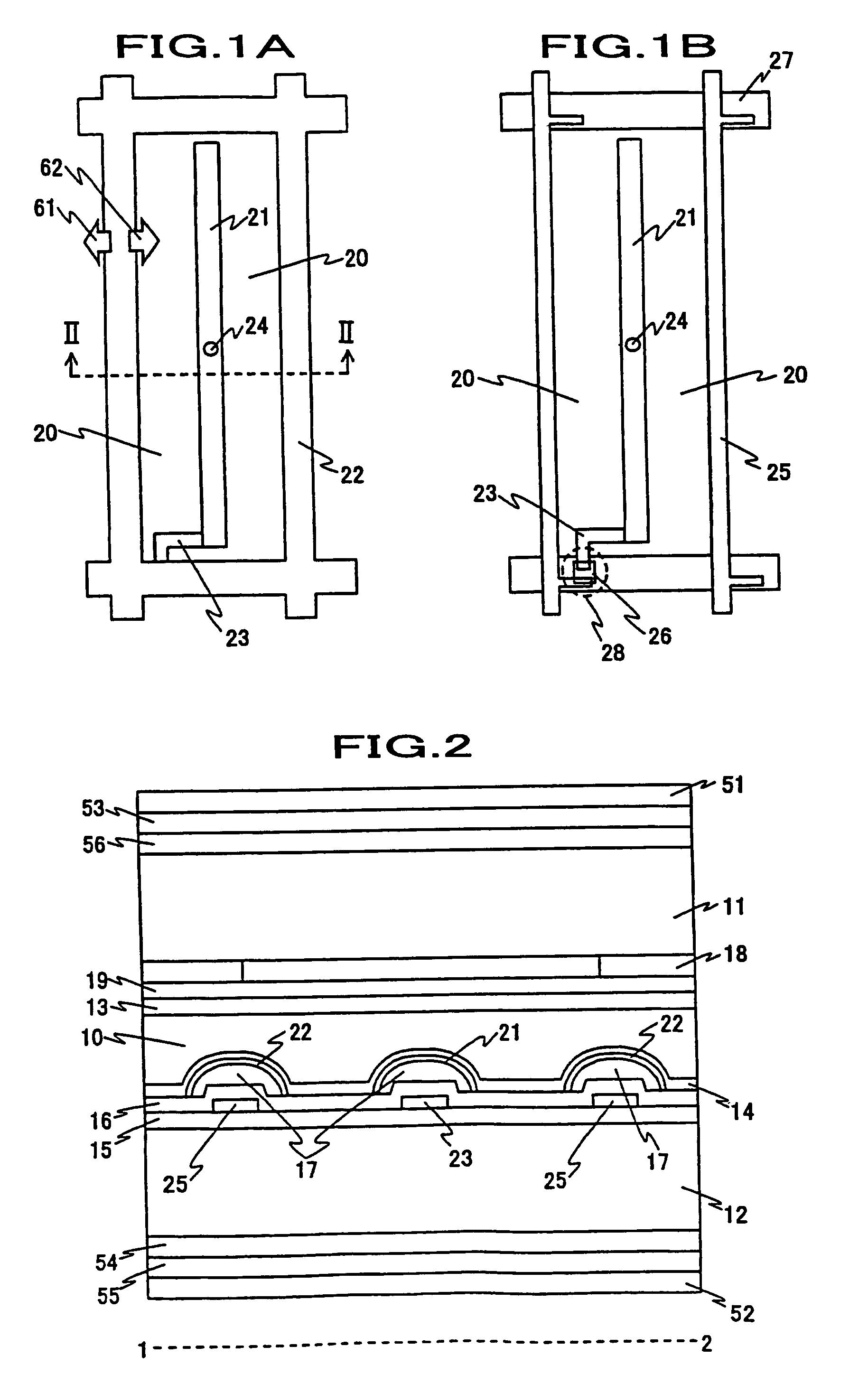
[0067]The cross sectional view of the present LCD panel is shown in FIG. 2 and the top view of the second substrate 12 is shown in FIG. 1. FIG. 2 shows a cut view in the dotted line II-II shown in FIG. 1 and the first substrate 11 and the second substrate 12 suspend the liquid crystal layer 10 therebetween. The first substrate 11 has an alignment layer 13, leveling layer 19 and the color filter 18 in the side adjacent to the liquid crystal layer 10.

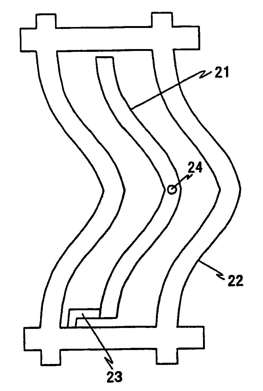
[0068]FIG. 1A shows the pattern of the common electrode 22 on the second substrate 12 and FIG. 1B shows the layer pattern underneath the electrode 22. The second substrate 12 has the second alignment layer 13 in the side close to the liquid crystal layer 10 and has thin film transistor 28. The thin film transistor 28 has the construction of anti-stager and the channel is made of the amorphous silicon layer 26.

[0069]The scanning lines 27 and the signal lines 25 are crossing and the thin film transistor 28 locates thereon. The thin film tra...

second embodiment

[0104]FIG. 8 shows another embodiment of the present invention wherein the pixel electrode 21 and the common electrode 22 have the different cross sectional form by which the reflection characteristics are improved. The cross section of the pixel electrode 21 and the common electrode 22 is symmetry, which is same as the embodiment 1. The flat area is relatively reduced in comparison to the embodiment 1 and the slope area is increased.

[0105]The pixel electrode 21 and the common electrode 22 are made in the flowing method. The insulator 17 is patterned by using a grating mask which enables to progressively adjust exposure. The exposure is fully done onto the gaps between comb like electrodes and the insulation film is completely removed. The edge portions of the comb like electrodes 21 and 22 are incompletely exposed and rather thin insulation film is left. Since the central area of the comb like electrodes 21 and 22 is not exposed, the rather thick insulation film is left. The left i...

third embodiment

[0108]As shown in FIG. 9, the cross section of the pixel electrode 21 and the common electrode 22 is formed in asymmetric. The decrease of the flat surface is same as the second embodiment but the flat portion is not on the central portion of the pixel electrode 21 and the common electrode 22.

[0109]The asymmetric cross section is formed in the following manufacturing process. By using grating mask as well as the second embodiment, the deviated portion on the comb like electrodes 21 and 22 is not exposed and thick insulation film is left. Other than this process, an additional organic insulating film is formed selectively to the central areas and the film is melted into the similar shape of the cross section.

[0110]According to the asymmetric shape of the cross section, higher rate of reflective scattering toward the normal direction for the incident lights from the slant direction of the one side of the cross section than the conventional LCD panel. The display even in the bright cir...


PUM

PropertyMeasurementUnit
thicknessaaaaaaaaaa
thicknessaaaaaaaaaa
wave lengthaaaaaaaaaa

Abstract

The comb like electrodes to drive the orientation of the liquid crystal through the lateral electric field in the IPS (In plane Switching) LCD panel has a construction that the comb like electrodes are optically reflective, are projections in the gap area and have curved surfaces in the cross section of the electors.

Description

FIELD OF THE INVENTION[0001]The present invention relates to a transflective liquid crystal display panel that has wide viewing angle.BACKGROUND OF THE INVENTION[0002]Transflective liquid crystal display panels that have schemes of wide viewing angle as well as IPS (In Plane Switching) and VA (Vertical Alignment) are now-a-day popularly used and being used for liquid crystal display TVs with additional improvement of moving picture characteristics. On the other hand, the liquid crystal display (called “LCD” hereinafter) has been widely used for portable information devices such as portable phones and digital cameras. The display panels for these portable information devices are simultaneously used by one person or a few persons and therefore wide viewing angle seems not to be necessary. However considering to the application of the digital cameras, wide viewing angle is still required since the monitoring is done from the view of slant back direction. For keeping privacy of the data...

Claims


Application Information

Patent Timeline
Patent Type & Authority Patents(United States)
IPC IPC(8): G02F1/1343G02F1/1335G02F1/13363
CPCG02F1/134363G02F1/133555
Inventor ITOU, OSAMUABE, MAKOTO
Owner PANASONIC LIQUID CRYSTAL DISPLAY CO LTD
Why Eureka
Try Eureka