Method, apparatus, and program for judging faces facing specific directions

a technology of specific directions and methods, applied in the field of methods, apparatuses, and programs for detecting faces facing specific directions, can solve the problems of low detection rate, inapplicability of classifiers to cases, and inability to detect all faces using these types of classifiers, and achieve the effect of high detection ra

Inactive Publication Date: 2007-08-23
FUJIFILM CORP
View PDF0 Cites 23 Cited by
  • Summary
  • Abstract
  • Description
  • Claims
  • Application Information

AI Technical Summary

Benefits of technology

[0013]The present invention has been developed in view of the foregoing circumstances. It is an object of the present invention to provide a method, apparatus, and program for detecting faces facing specific directions, capable of detecting faces in a highly discriminatory manner with respect to the facing direction while achieving a high detection rate.

Problems solved by technology

These classifiers are not applicable to cases in which the shapes of faces differ.
Therefore, there is a problem that detection using these types of classifiers does not detect all faces facing the specific direction within an image.
That is, the detection rate becomes low when these types of classifiers are used.
The angular ranges of faces, which are judgment targets of classifiers generated in this manner, tend to be wider, and there is a problem that detection in a discriminatory manner is not possible by using these classifiers.
Therefore, it is difficult for a large degree of tolerance and a narrow angular range to be compatible in face classifiers.
If faces facing specific directions are to be detected from within images by using face classifiers, it is difficult to achieve a high detection rate simultaneously with highly discriminatory detection with respect to the specific directions.
However, the classifier is not capable of detecting faces having various shapes, and therefore the detection rate is low.
However, the detectable range of the classifier becomes greater than the range of specific facing directions to be detected, and detection of faces facing a specific direction cannot be performed in a highly discriminatory manner.

Method used


Image

  • Method, apparatus, and program for judging faces facing specific directions
  • Method, apparatus, and program for judging faces facing specific directions
  • Method, apparatus, and program for judging faces facing specific directions

Examples


Embodiment Construction

[0052]Hereinafter, an embodiment of the present invention will be described with reference to the attached drawings.

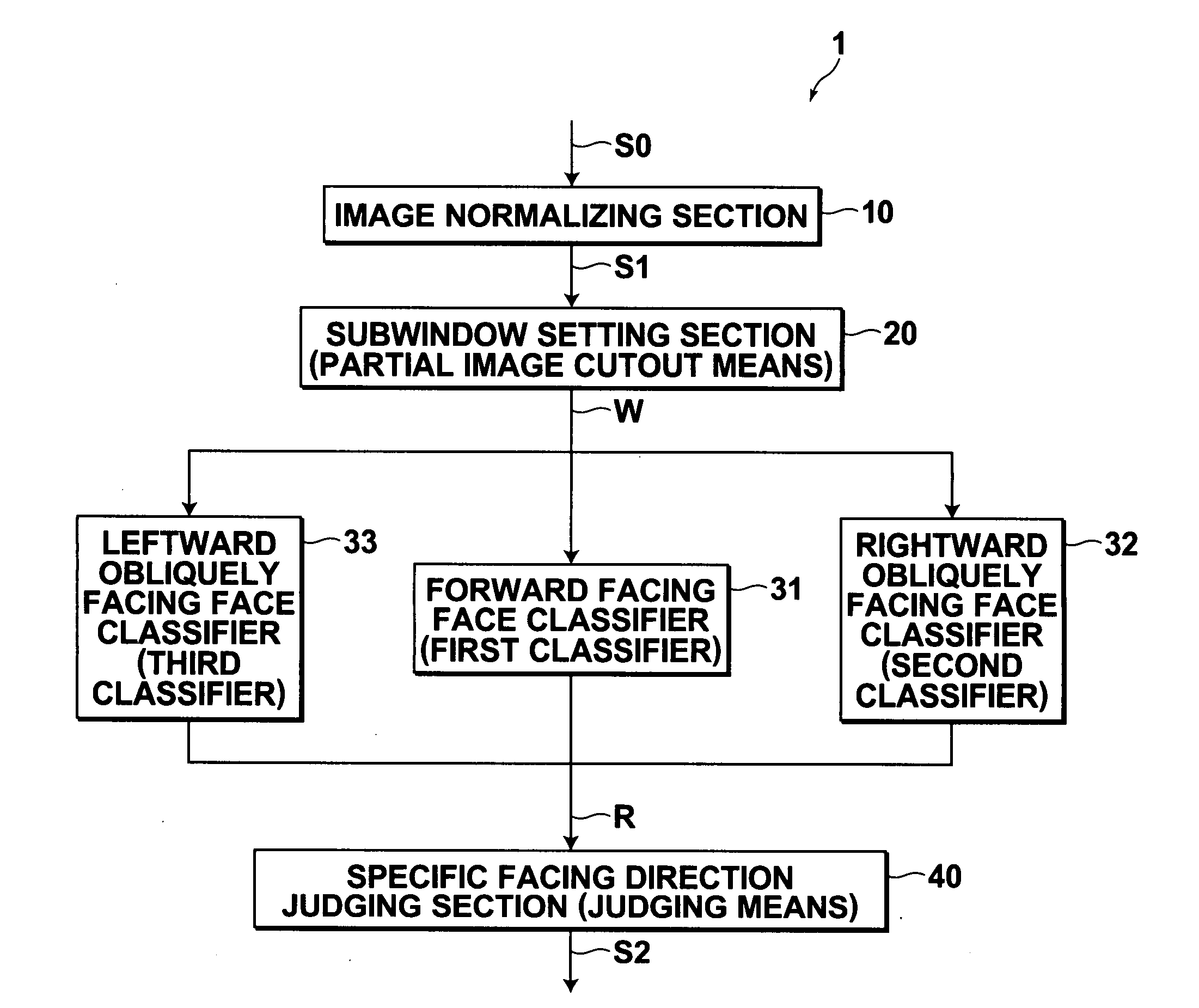
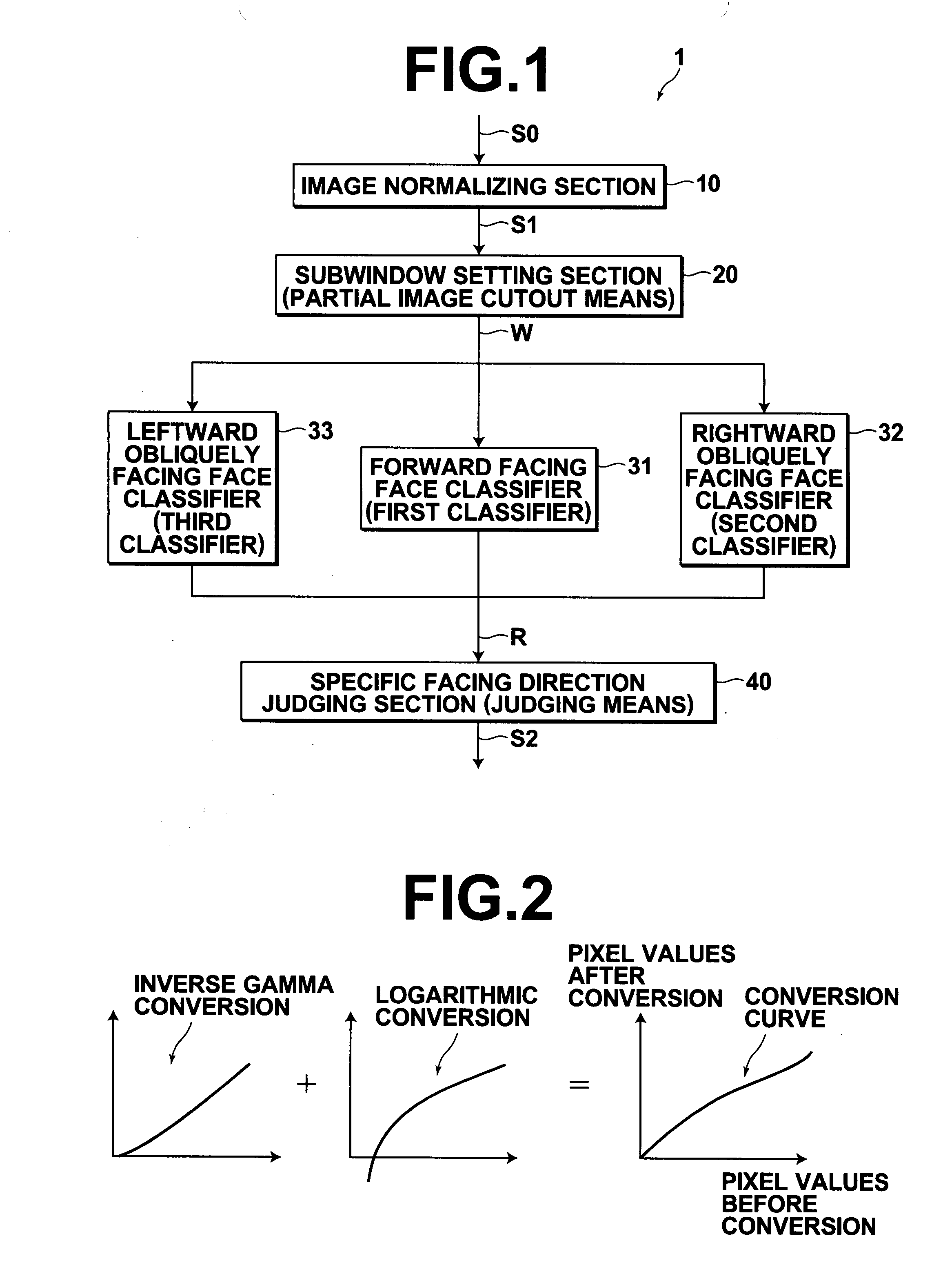
[0053]FIG. 1 is a schematic block diagram that illustrates the construction of a specific facing direction face detecting system 1 according to an embodiment of the present invention. As illustrated in FIG. 1, the specific facing direction face detecting system 1 comprises: an image normalizing section 10; a subwindow setting section 20 (partial image cutout means); a forward facing face classifier 31 (first classifier); a rightward obliquely facing face classifier 32 (second classifier); a leftward obliquely facing face classifier 33 (third classifier); and a specific facing direction face judging section 40 (judging means).

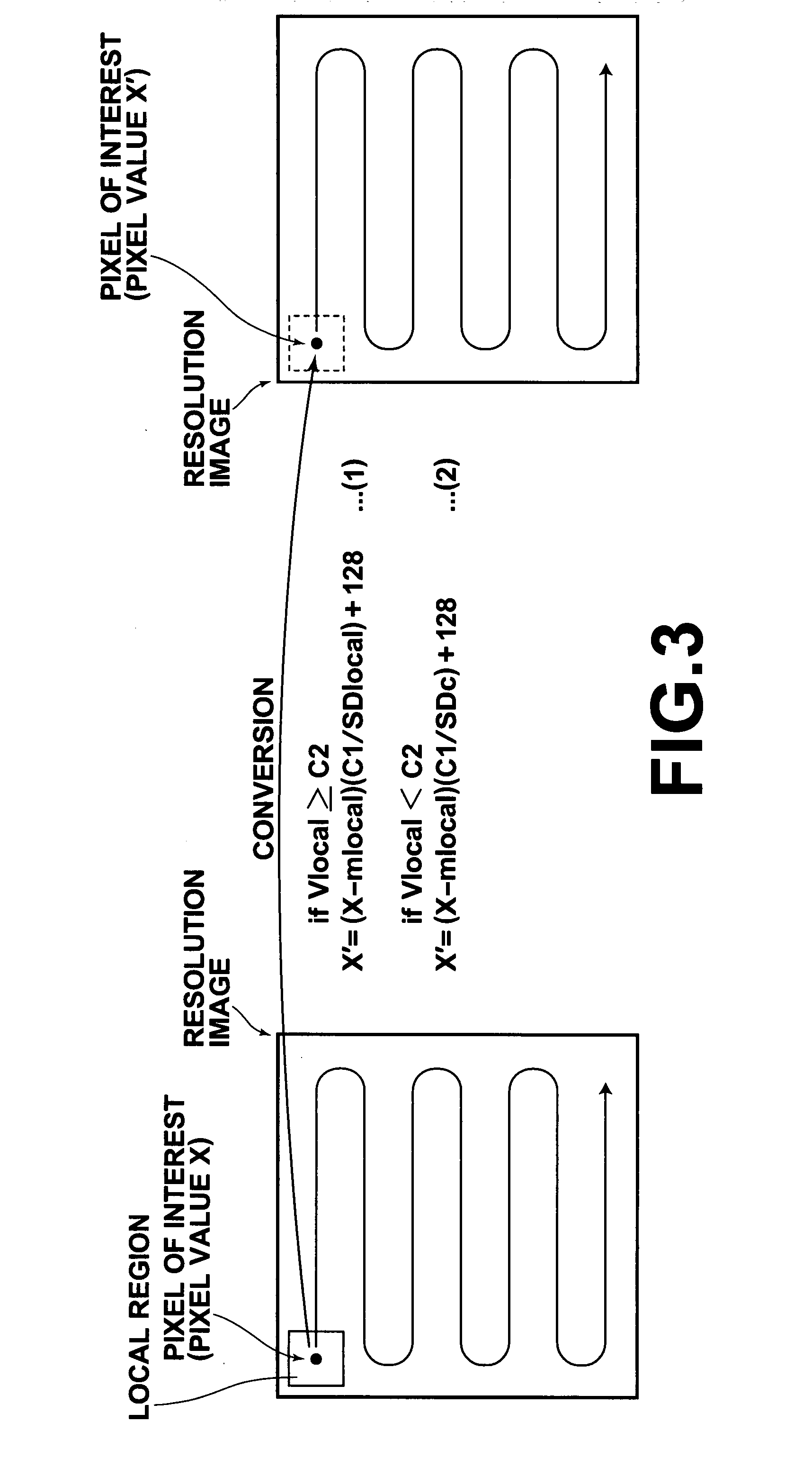
[0054]The image normalizing section 10 administers normalizing processes on input images S0, such that the contrast therein is suitable for face detection, and obtains normalized images S1. The normalizing processes comprise a global normalizing pr...


PUM


Abstract

A partial image is cut out from an input image. A first classifier judges whether the partial image includes a face facing a direction within a first angular range. Another classifier judges whether the partial image includes a face facing a direction within another angular range that partially overlaps with the first angular range. The partial image is judged to include a face facing a direction within a specific angular range, which is the first angular range from which the portion that overlaps with the other angular range has been removed, if the first classifier judges that the image includes a face facing a direction within the first angular range, and the other classifier judges that the image does not include a face facing the second angular range. Each classifier is generated by machine learning, and judges whether images include faces facing directions corresponding to predetermined angular ranges.

Description

BACKGROUND OF THE INVENTION[0001]1. Field of the Invention[0002]The present invention relates to a method, an apparatus, and a program for detecting faces facing specific directions from within digital images.[0003]2. Description of the Related Art[0004]Conventionally, techniques for detecting faces included in digital images (hereinafter, simply referred to as “images”) are utilized in various fields, such as digital cameras and authenticating systems. However, there are cases in which a technique that detects only faces facing specific directions within images is desired.[0005]As a method for detecting only faces facing specific directions, a method, in which partial images are cut out from a plurality of different positions within an image, and whether each of the partial images includes a face facing the specific directions is judged, may be considered. To perform the judgments, the use of classifiers, which are generated by a machine learning method employing sample images, are...

Claims


Application Information

Patent Timeline
Patent Type & Authority Applications(United States)
IPC IPC(8): G06K9/62
CPCG06K9/6292G06K9/00288G06V40/172G06V10/809G06F18/254
Inventor YAMAGUCHI, YOSHITAKA
Owner FUJIFILM CORP
Why Eureka
Try Eureka