Imaging lens and imaging device

a technology of imaging lens and lens body, applied in the field of imaging lens and imaging device, can solve the problems of unfavorable unfavorable lens cost and high cost drawback, and achieve the effect of superior optical performan

Active Publication Date: 2008-07-24
TIANJIN OFILM OPTO ELECTRONICS CO LTD
View PDF2 Cites 25 Cited by
  • Summary
  • Abstract
  • Description
  • Claims
  • Application Information

AI Technical Summary

Benefits of technology

[0008]An object of an illustrative, non-limiting embodiment of the invention is to provide an imaging lens which is compact, wide-angle, bright, and inexpensive and which also maintains superior optical performance, as well as providing an imaging device equipped with the imaging lens.

Problems solved by technology

U.S. Pat. No. 7,023,628 describes a bright lens having an F number of 2, but the lens frequently uses a glass material whose refractive index exceeds a value of 1.9 and hence has a drawback of high cost.
When the lens is formed by using glass as a material, the lens also becomes expensive unfavorably.

Method used


Image

  • Imaging lens and imaging device
  • Imaging lens and imaging device
  • Imaging lens and imaging device

Examples


first example

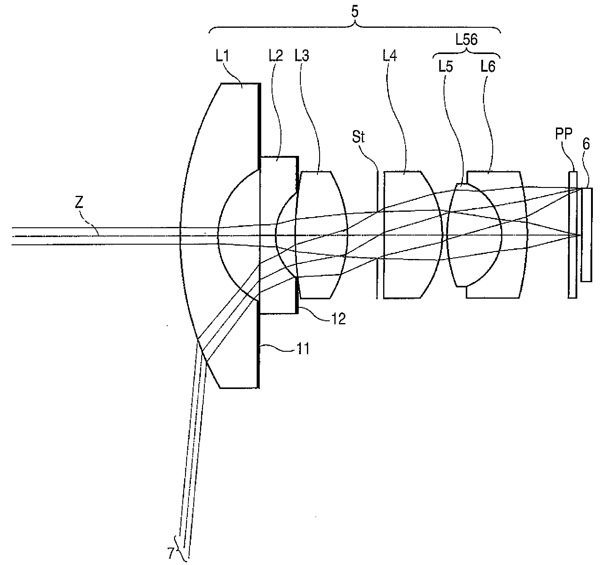
[0077]Table 1 shows values of specifications, design specifications, and focal lengths of the imaging lens of the first example. In Table 1, Si designates the i-th surface number (“i”=1 through 15) which gradually increases toward the image side while the surface of a constituent element located most closely to the object side is taken as the first. Ri designates a radius of curvature of the i-th plane (“i”=1 through 15). Di designates on-axis surface spacing between the i-th plane (“i”=1 through 14) and the i+1th plane along the optical axis Z. Ndj designates a refractive index of the j-th (j=1 through 7) lens, the number of which gradually increases toward the image side while the lens positioned most closely to the object side is taken as the first, or the optical member PP at the d-line (587.6 nm); and vdj designates an Abbe number of the jth lens or the optical member PP at the d-line. Nd7 designates a refractive index of the optical member PP, and vd7 designates an Abbe number...

second example

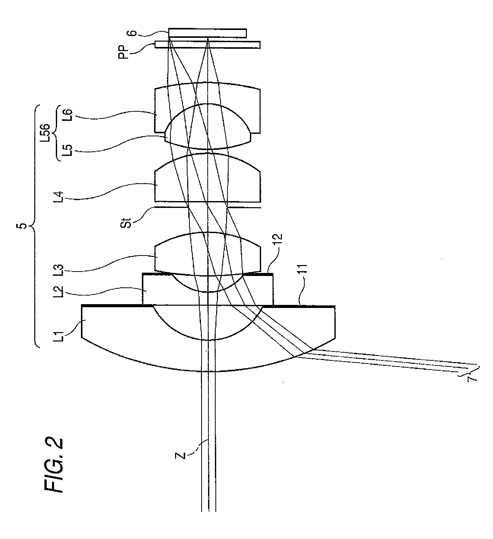
[0080]Table 2 shows values of specifications of an imaging lens of a second example, and FIG. 4 shows a block diagram of the lens. In FIG. 4, reference symbols Ri and Di correspond to Ri and Di of Table 2.

TABLE 2Example 2SiRiDiNdjνdj 119.311.941.834842.7 24.342.11 3∞0.801.772549.6 42.810.87 515.912.681.834037.2 6−6.791.55 7 (Aperture∞0.34Diaphragm) 8246.123.001.755052.3 9−5.150.24108.612.851.713053.911−2.921.341.922918.912−15.572.7713∞0.401.516864.214∞0.2515 (Imaging∞Surface)L′21.1L21.0FNo.2.02ω136.8f2.1f12−2.0f5614.3f123−8.3f4564.7

third example

[0081]Table 3 shows values of specifications of an imaging lens of a third example, and FIG. 5 shows a block diagram of the lens. In FIG. 5, reference symbols Ri and Di correspond to Ri and Di of Table 3.

TABLE 3Example 3SiRiDiNdjνdj 120.001.201.516864.2 25.003.52 3−573.000.801.516864.2 42.793.06 523.051.551.834842.7 6−11.081.92 7 (Aperture∞0.13Diaphargm) 8−11.912.791.755052.3 9−5.300.15105.422.811.713053.911−3.501.761.922918.912−16.532.2213∞0.401.516864.214∞0.2515 (Imaging∞Surface)L′22.6L22.4FNo.2.02ω166.0f1.8f12−3.2f568.1f123−20.7f4564.5


PUM


Abstract

The imaging lens is provided and includes: in order from the object side, a negative first lens whose concave surface is directed toward the image side; a second lens of a planoconcave lens whose flat surface is directed toward the object side or a biconcave lens whose surface having a larger absolute value of radius of curvature is directed toward the object side; a third biconvex lens; a stop; a positive fourth lens whose surface having a smaller absolute value of radius of curvature is directed toward the image side; and a cemented lens of a positive fifth lens of biconvex shape and a negative sixth lens of meniscus shape, the cemented lens having a positive refractive power, and an Abbe number v3 at d-line of the third lens satisfies a conditional expression (1) v3<43.

Description

BACKGROUND OF THE INVENTION[0001]1. Field of the Invention[0002]The present invention relates to an imaging lens and an imaging device equipped with the imaging lens, and more particularly to a wide angle imaging lens suitable for use in an onboard camera, a camera for a portable terminal, a surveillance camera, and the like, using an imaging element, such as a CCD (Charge-Coupled Device), CMOS (Complementary Metal Oxide Semiconductor), or the like, as well as to an imaging device equipped with the imaging lens.[0003]2. Description of Related Art[0004]An extreme progress has recently been made in miniaturization and an increase in the number of pixels of an imaging element, such as a CCD and CMOS. In step with such a progress, miniaturization of a main body of imaging equipment having the imaging element has also advanced, and miniaturization of the imaging lens incorporated into the imaging equipment is also sought.[0005]Meanwhile, in relation to an onboard camera or a surveillance...

Claims


Application Information

Patent Timeline
Patent Type & Authority Applications(United States)
IPC IPC(8): G02B9/62
CPCG02B13/06
Inventor ASAMI, TARO
Owner TIANJIN OFILM OPTO ELECTRONICS CO LTD
Why Eureka
Try Eureka