

Projection optical system and image projection apparatus
- Summary
- Abstract
- Description
- Claims
- Application Information
AI Technical Summary
Benefits of technology
Problems solved by technology
Method used
Image

Examples
first embodiment
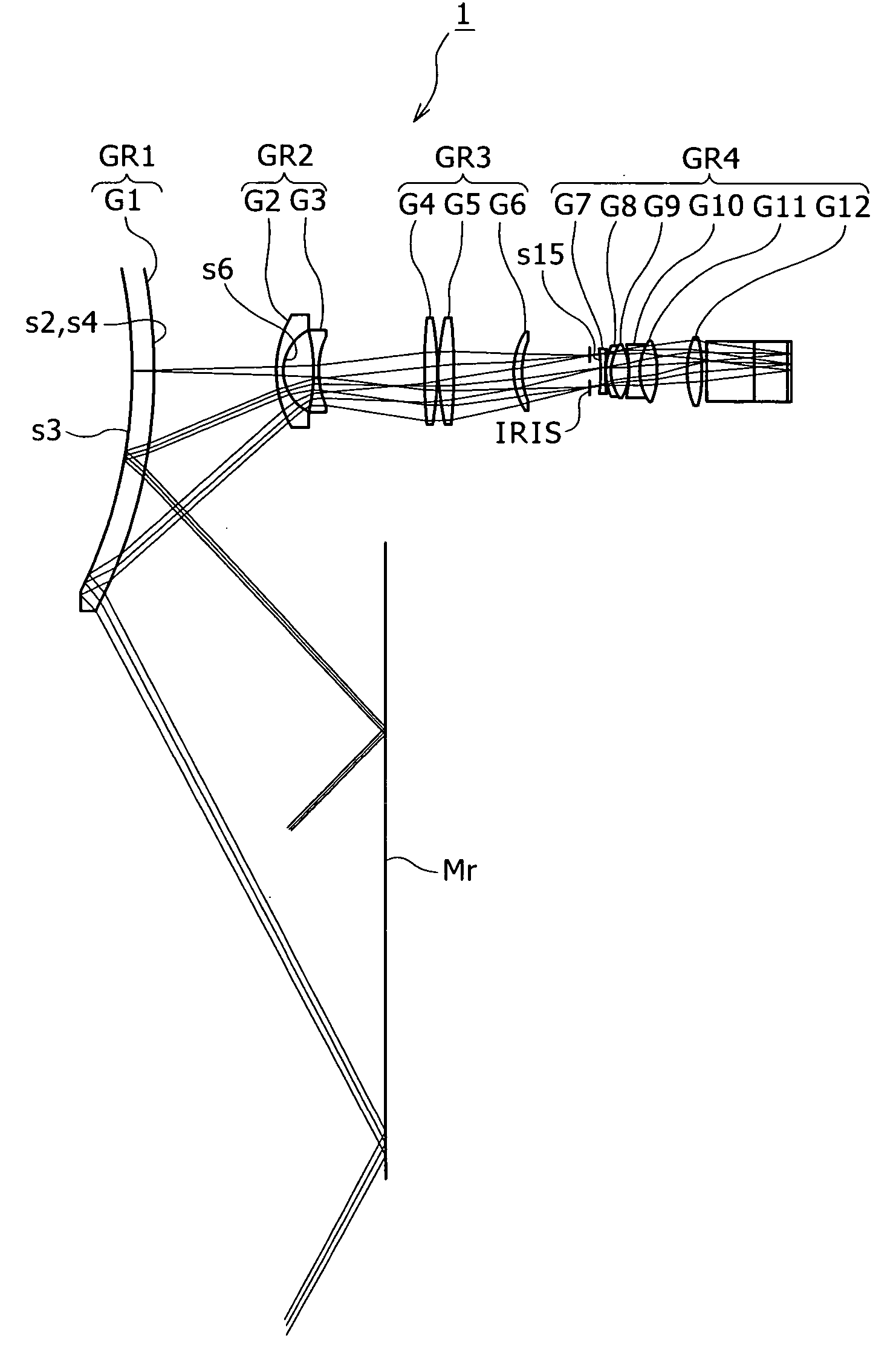
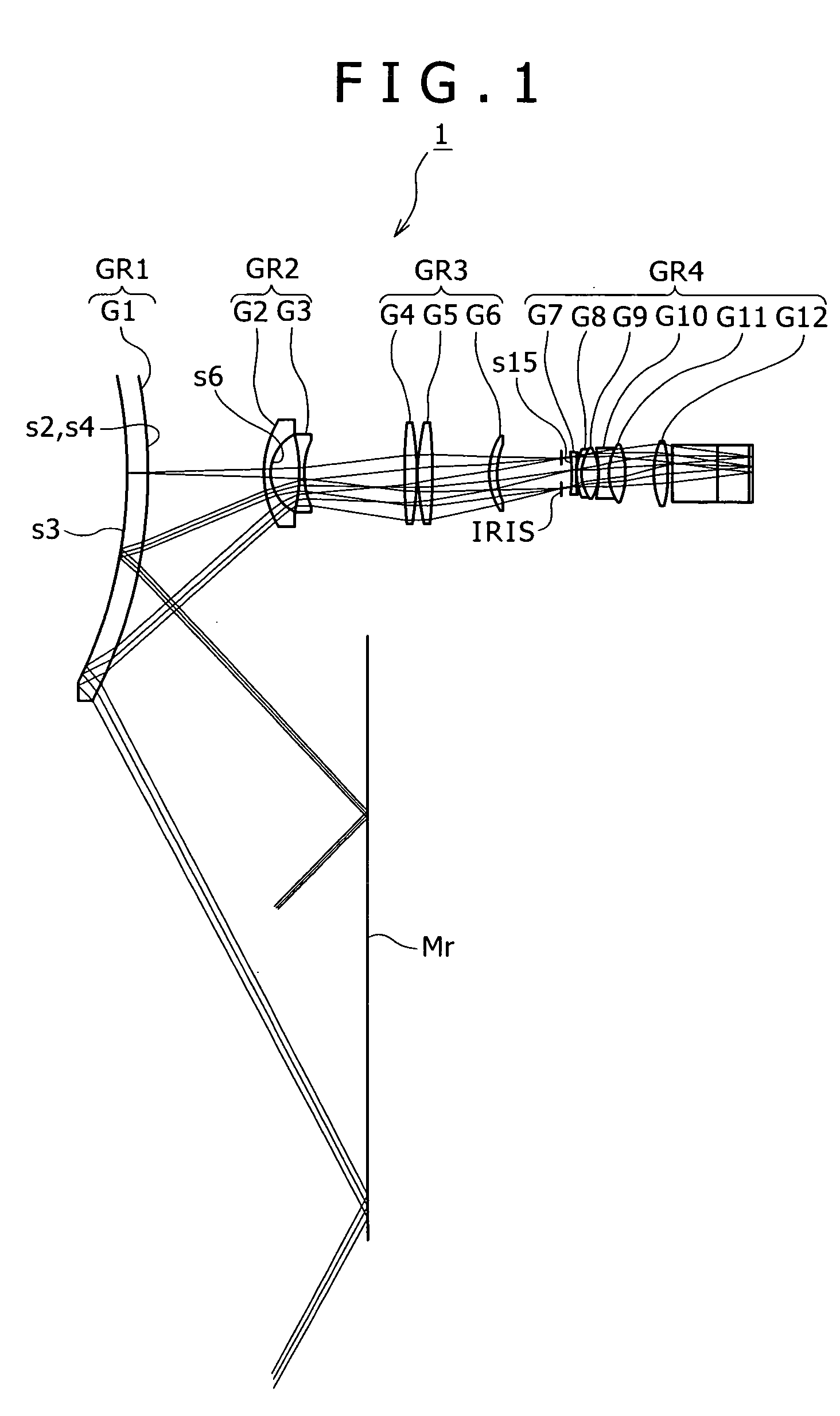
[0057]FIG. 1 shows a lens system of the projection optical system according to the present invention.
[0058] Referring to FIG. 1, the projection optical system 1 shown includes a first lens group GR1 composed of a negative meniscus lens G1 having a concave surface directed to the projection side, a second lens group GR2 having a negative refracting power, a third lens group GR3 having a positive refracting power and a fourth lens group GR4 having a positive refracting power, disposed in order from the projection side. Thus, the projection optical system 1 has a lens configuration of the four-group retrofocus type.
[0059] The concave surface (face on the projection side) s3 of the negative meniscus lens G1 which composes the first lens group GR1 is formed as a reflecting surface having an aspherical shape, and a convex surface (face on the image side) s2, s4 of the negative meniscus lens G1 is formed as a refracting surface of an aspherical shape. The second lens group GR2 includes a ...
second embodiment
[0092]FIG. 3 shows a lens system of the projection optical system 2 according to the present invention.
[0093] Referring to FIG. 3, the projection optical system 2 shown includes a first lens group GR1 composed of a negative meniscus lens G1 having a concave surface directed to the projection side, a second lens group GR2 having a negative refracting power, a third lens group GR3 having a positive refracting power and a fourth lens group GR4 having a positive refracting power, disposed in order from the projection side. Thus, the projection optical system 2 has a lens configuration of the four-group retrofocus type.
[0094] The concave surface (surface on the projection side) s3 of the negative meniscus lens G1 which composes the first lens group GR1 is formed as a reflecting surface having an aspherical shape, and a convex surface (surface on the image side) s2, s4 of the negative meniscus lens G1 is formed as a refracting surface of an aspherical shape. The second lens group GR2 inc...
third embodiment
[0102]FIG. 5 shows a lens system of the projection optical system 3 according to the present invention.
[0103] Referring to FIG. 5, the projection optical system 3 shown includes a first lens group GR1 composed of a negative meniscus lens G1 having a concave surface directed to the projection side, a second lens group GR2 having a negative refracting power, a third lens group GR3 having a positive refracting power and a fourth lens group GR4 having a positive refracting power, disposed in order from the projection side. Thus, the projection optical system 3 has a lens configuration of the four-group retrofocus type.
[0104] The concave surface (face on the projection side) s3 of the negative meniscus lens G1 which composes the first lens group GR1 is formed as a reflecting surface having an aspherical shape, and a convex surface (face on the image side) s2, s4 of the negative meniscus lens G1 is formed as a refracting surface of an aspherical shape. The second lens group GR2 includes ...
PUM
 Abstract
Description
Claims
Application Information