
Data transmission system

a data transmission and data technology, applied in the field of data transmission systems, can solve the problems of large capacity of file, difficult to carry out large-capacity transfer of file or relaying of high-quality video, and large capacity of file to be subjected to transmission, and achieve the effect of large-capacity data transfer and short tim

Inactive Publication Date: 2008-03-04
SONY CORP
View PDF18 Cites 81 Cited by
  • Summary
  • Abstract
  • Description
  • Claims
  • Application Information

AI Technical Summary

Benefits of technology

[0007]An object of this invention is to provide a data transmission system, a data transmitting apparatus, a data receiving apparatus and a data transmission method adapted for transferring large capacity data in a short time.
[0008]Another object of this invention is to provide a data transmission system, a data transmitting apparatus, a data receiving apparatus and a data transmission method which can transfer moving picture data of high picture quality in a short time and can carry out relaying of moving picture of high picture quality in real time.

Problems solved by technology

In general, in the case where moving picture is digitized, capacity of file becomes very large.
However, in the conventional data delivery, there is the problem that it is difficult to carry out transfer of file of large capacity or relaying of video of high picture quality.
As a result, capacity of file to be subjected to transmission becomes very large.
In addition, also in data transmission of real time such that relaying of video is carried out, it is impossible to carry out transmission of data at such a transmission rate to exceed capacity of one transmission path.
For this reason, it was impossible to respond to needs to deliver moving picture data while maintaining high picture quality.

Method used


Image

  • Data transmission system
  • Data transmission system
  • Data transmission system

Examples


first embodiment

[0032]A moving picture transmission system according to the present invention is will be first described as this invention.

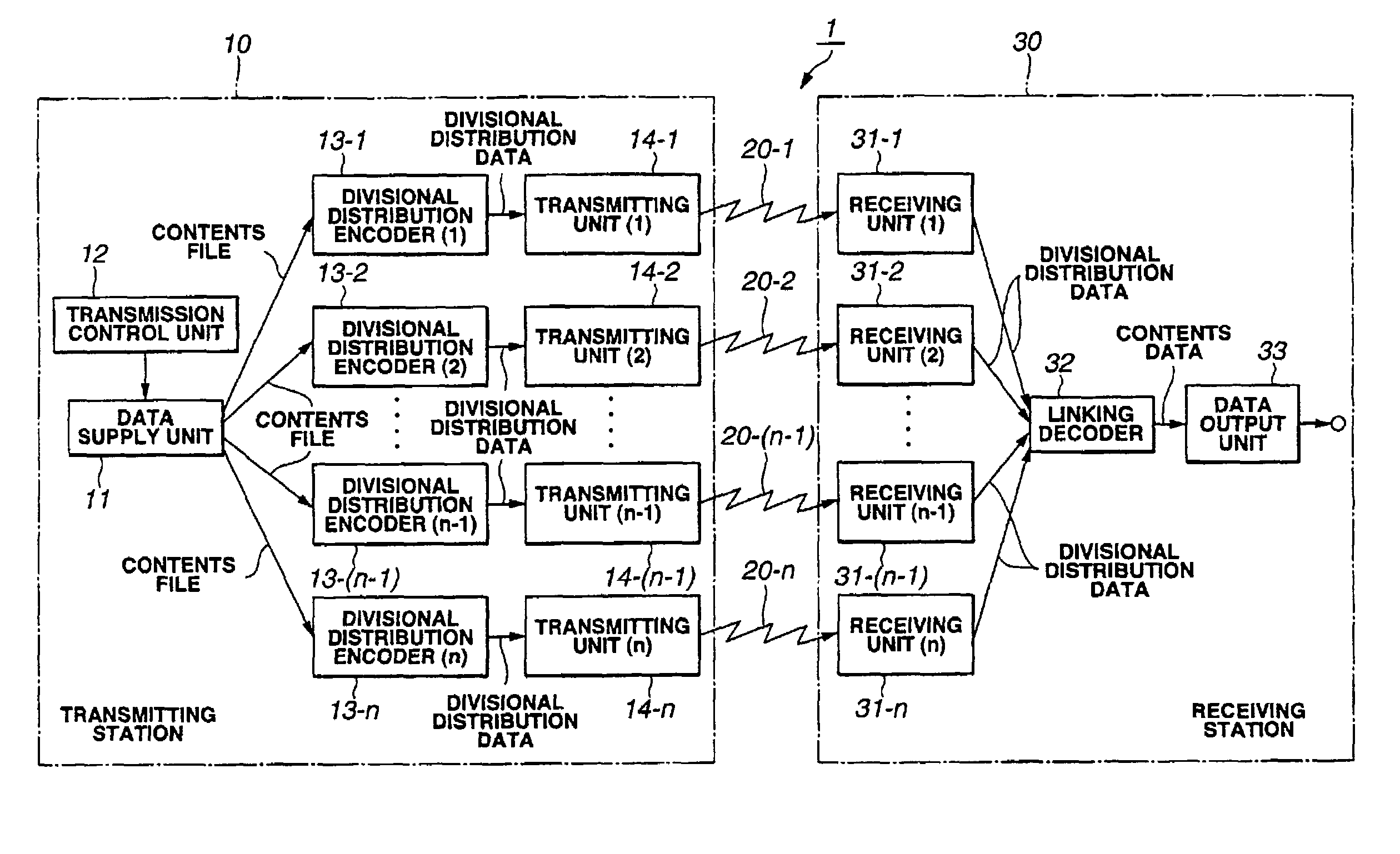
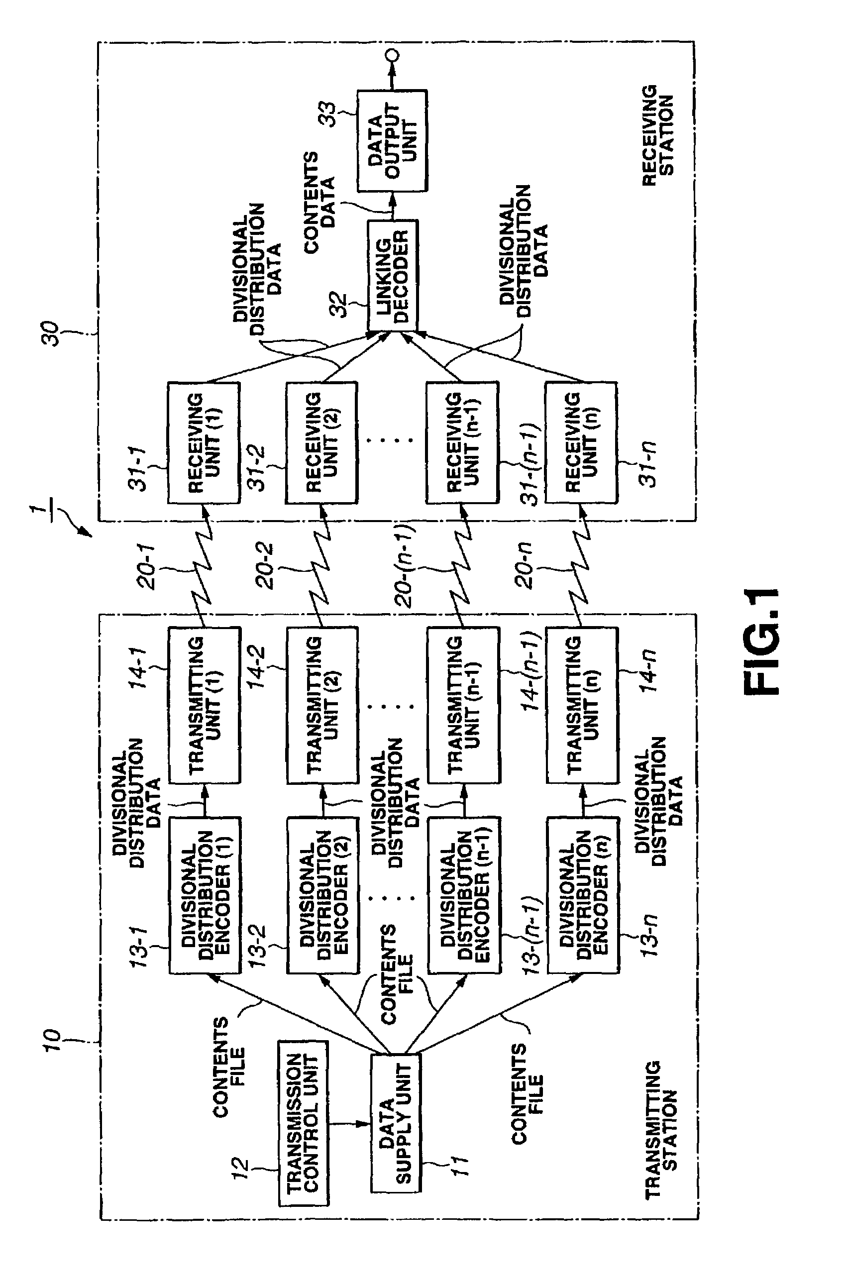
[0033]The system configuration of moving picture transmission system 1 which will be explained as the first embodiment is shown in FIG. 1.

[0034]The moving picture transmission system 1 comprises a transmitting station 10 for transmitting moving picture data through predetermined transmission paths, plural transmissions paths 20-1 to 20-n, and a receiving station 30 for receiving moving picture data transmitted through the respective transmission paths 20-1 to 20-n. It is to be noted that while in the case where this moving picture transmission system 1 is applied to, e.g., transmission between relay stations, etc., the system is constituted by one transmitting station 10 and one receiving station 30, in the case where this moving picture transmission system 1 is applied to, e.g., multicast transmission, etc., the system is constituted by one transmitting station...

second embodiment

[0062]Explanation will now be given in connection with the data transmission system according to this invention as this invention.

[0063]The system configuration of the data transmission system 100 which will be explained as the second embodiment is shown in FIG. 5.

[0064]The data transmission system of the second embodiment comprises a data transmitting station 110 which is a data transmitting apparatus and a data receiving station 120 which is a data receiving apparatus. In this data transmission system 100, the system may be constituted by one data transmitting station 110 and plural data receiving stations 120, or may be constituted by one data transmitting station 110 and one data receiving station 120.

[0065]The data transmitting station 110 comprises a data supply unit 111 serving as data supply means, a transmission control unit 112 serving as transmission control means, and data transmission units 113-1, 113-2 . . . , 113-n serving as data transmitting means.

[0066]The data sup...


PUM


Abstract

A transmission control unit (12) of a transmitting station (10) specifies usable plural transmission paths (20). A data supply unit (11) transfers movie contents file encoded by MPEG 4 to plural divisional distribution encoders (13) corresponding to the specified plural transmission paths (20). The respective divisional distribution encoders (13) divide movie contents file into plural divisional distribution data in which original data file can be restored by carrying out synthesis. Further, the transmitting station (10) transmits divided respective divisional distribution data through transmission paths different from each other. Respective receiving units (31) of a receiving station (30) respectively receive divisional distribution data from the plural transmission paths (20). A linking decoder (32) synthesizes plural divisional distribution data to restore original movie contents file. Thus, high speed transfer of contents file of large capacity can be carried out.

Description

TECHNICAL FIELD[0001]This invention relates to a data transmission system, a data transmitting apparatus, a data receiving apparatus and a data transmission method for transmitting data files of large capacity through a satellite wave, a ground wave or a cable, etc., and, for example, relates to the data transmission system, the data transmitting apparatus, the data receiving apparatus and the data transmission method used in, e.g., multi-cast distribution or data transmission between relay stations, etc. of moving picture data of movie or television program, etc.BACKGROUND ART[0002]In recent years, cases where data delivery of large capacity file is required have been increased. For example, moving pictures (movie, video, television program, etc.) which could been only handled as analog data in the prior art are being digitized. In general, in the case where moving picture is digitized, capacity of file becomes very large. For this reason, in digital broadcasts such as typical tele...

Claims


Application Information

Patent Timeline
IPC IPC(8): H04N7/173H04L45/24H04N5/00H04N7/16H04N7/24
CPCH04L29/06H04L45/00H04L45/24H04N7/16H04N21/234318H04N21/238H04N21/2385H04N21/4385H04N21/4622H04L65/4076H04L67/06H04L29/06027H04L69/14H04L65/611H04L45/243H04L9/40H04L65/1101
Inventor KUBOTA, ICHIROKAMIYA, SHIGEKI
Owner SONY CORP
Learn More