Electric power supply system for vehicle

a technology for electric power supply and vehicles, applied in the field of electric power supply systems, can solve the problems of limit to the overall capacity of batteries that can be loaded into a single vehicle, limit to the maximum mileage a vehicle can do per charging, limit to the overall capacity of batteries, etc., and achieve the effects of simple configuration, good stability, and reduced cos

Active Publication Date: 2011-05-19
PANASONIC CORP
View PDF13 Cites 257 Cited by
  • Summary
  • Abstract
  • Description
  • Claims
  • Application Information

AI Technical Summary

Benefits of technology

[0018]An electric power supply system for vehicle according to the present invention can get charging and powering done with good stability even if the vehicle's position has shifted significantly and even though the system has a simple configuration. As a result, a lighter system can be provided at a reduced cost. On top of that, the electric power supply system for vehicle of the present invention with such stabilized charging and powering capabilities can also simply the circuit configuration by omitting some circuit blocks such as DC / DC converter and a regulator. Consequently, the overall powering efficiency will improve and charging and powering can be done in a shorter time.

Problems solved by technology

Meanwhile, considering the overall weight and cost of batteries, there is definitely a limit to the overall capacity of batteries that can be loaded into a single vehicle.
And that limit to the overall capacity of batteries directly leads to the maximum mileage a vehicle can do per charging.
However, since the resonant magnetic coupling method requires that k≠1 unlike the electromagnetic induction method in which k≈1, power cannot be transmitted with high efficiency unless inter-block impedance matching is kept achieved between the oscillation section and the power transmitting antenna and between the rectification section and the power receiving antenna.
In both of the system for charging and powering a running vehicle and the system for charging and powering a parked vehicle, the stability of transmission could be lost due to a relative positional shift between the power transmitting and receiving antennas.
Specifically, in the system for charging and powering a vehicle by resonant magnetic coupling, if the relative position of the power receiving antenna in a running or parked vehicle to the power transmitting antenna shifts horizontally with respect to the traveling direction of the vehicle, the power transmission by resonant magnetic coupling would lose its stability.
According to the technique disclosed in that patent document, however, the number of antennas to provide should be increased, thus raising the cost significantly.
On top of that, since charging and powering should not be done efficiently that way, it is difficult to apply such a technique to a system for charging and powering a running vehicle.
However, if such an unrealistic restriction were imposed, the advantage to be achieved by adopting such a non-contact charging and powering system would be sacrificed.
Nevertheless, Japanese Patent Application Laid-Open Publication No. 2009-106136 does not mention what problems will arise when a system for charging and powering a running or parked vehicle is established and provides no means for overcoming such problems.

Method used


Image

  • Electric power supply system for vehicle
  • Electric power supply system for vehicle
  • Electric power supply system for vehicle

Examples


embodiment 1

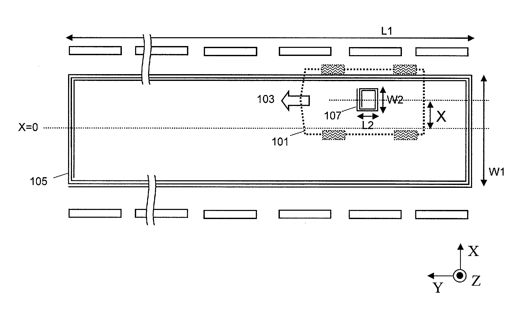
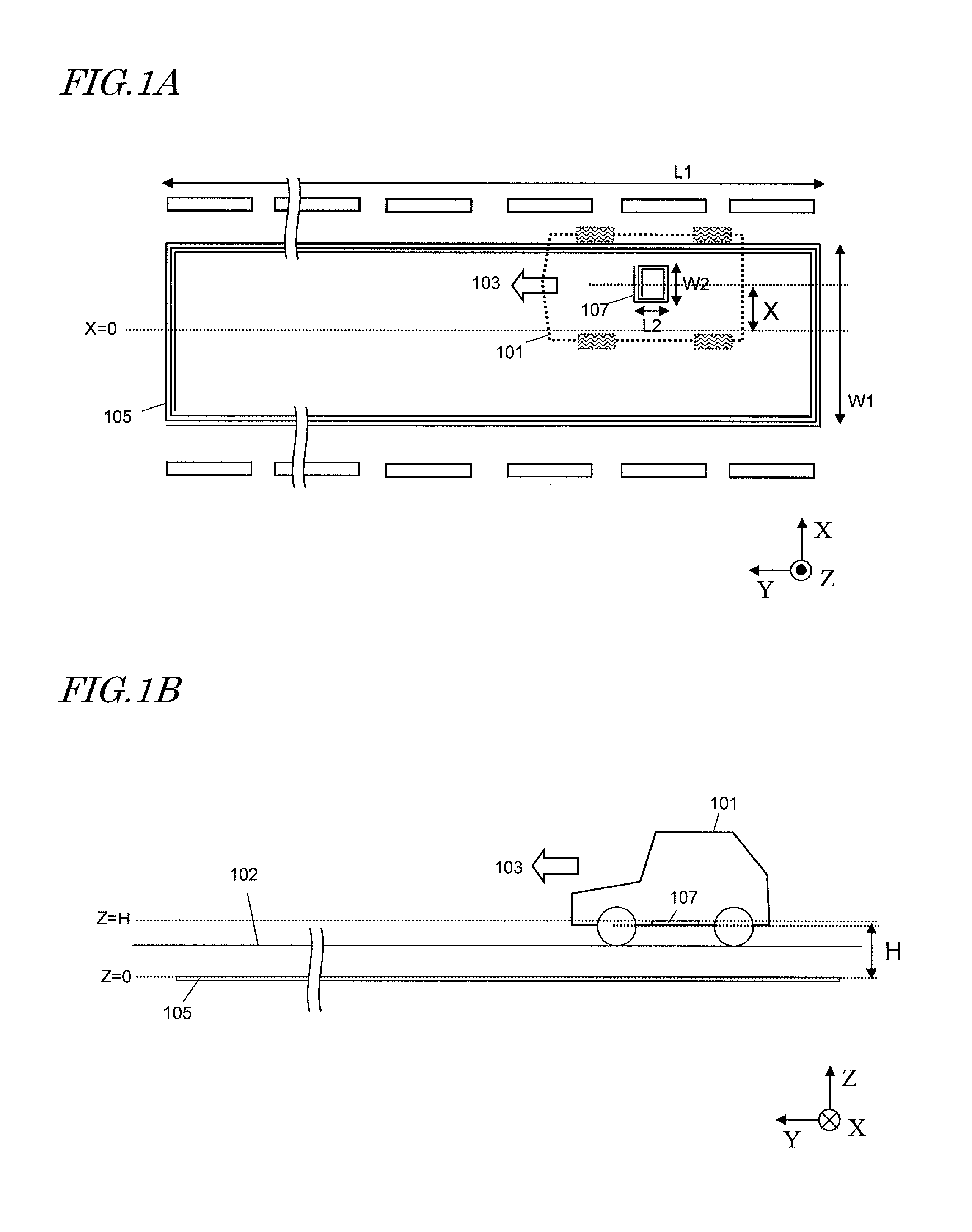
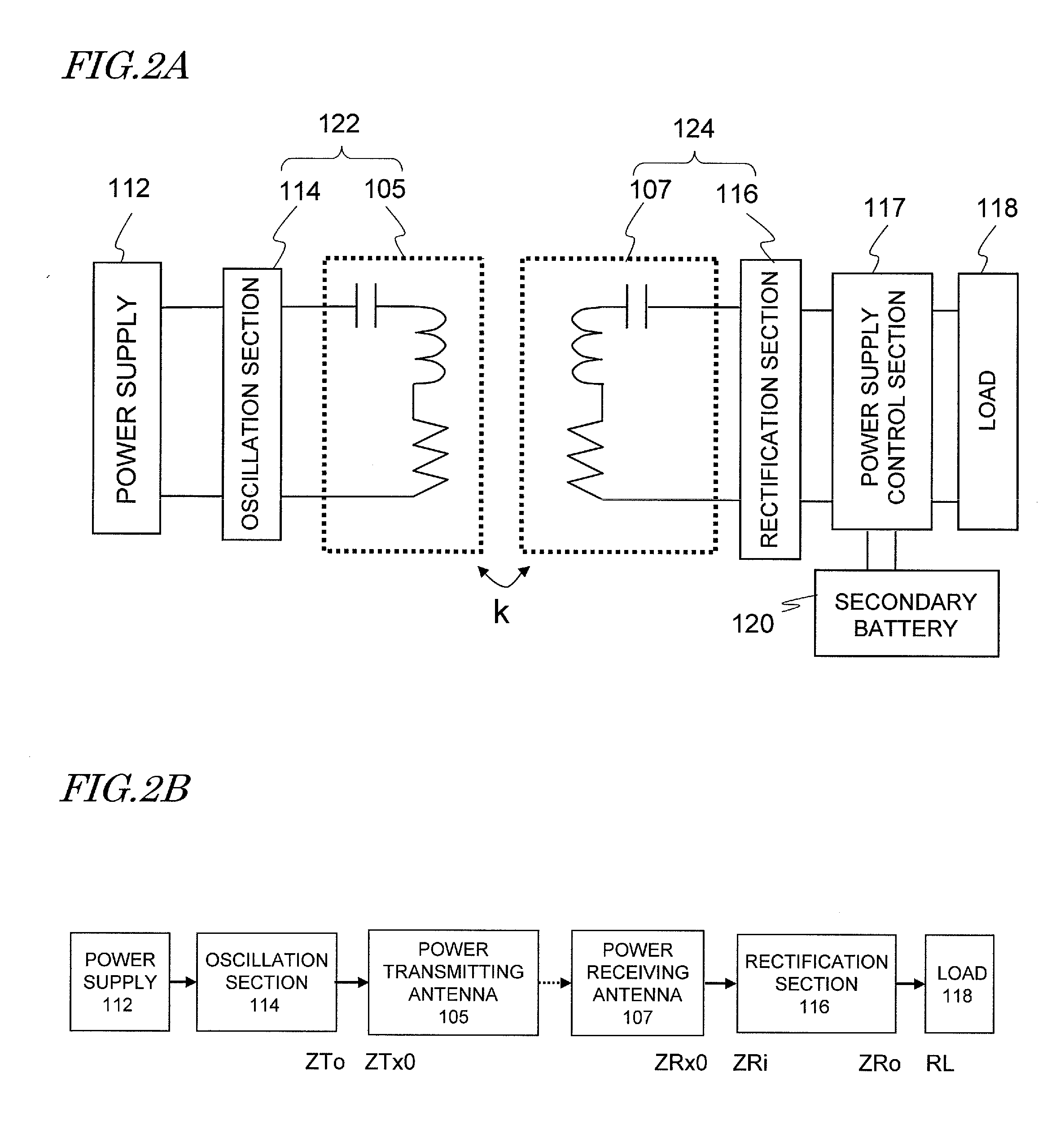
[0031]An Electric Power Supply System for Vehicle as a first specific preferred embodiment of the present invention is used as either an electric power supply system for the running vehicle for charging and / or powering a running vehicle or an electric power supply system for the parked vehicle for charging and / or powering a parked vehicle. As used herein, “to supply power” means “to charge” or “to power”. “To charge” means charging a secondary battery that is put in a vehicle and storing power to drive the vehicle, while “to power” means feeding electric power to a load (such as a driving electric motor) that is also built in the vehicle. An electric power supply system for vehicle according to this first preferred embodiment of the present invention includes a power transmitting antenna, which is provided on or under the ground, and a power receiving antenna, which is provided for the vehicle. These power transmitting and receiving antennas produce resonant magnetic coupling, there...

example 1

[0088]Hereinafter, specific examples of the present invention will be described.

[0089]To demonstrate the beneficial effect of the present invention, specific examples 1a and 1b of the electric power supply system for vehicle were made to have the arrangement shown in FIGS. 1A and 1B and analyzed. Specifically, in Example 1a, the electric power supply system for vehicle satisfied W1=250 cm, L1=1000 cm, and W2=L2=65 cm. On the other hand, in Example 1b, W1 and L1 had the same values as in Example 1a but W2 and L2 were changed to satisfy W2=43.3 cm and L2=86.7 cm. The power transmitting and receiving antennas were designed to have the same resonant frequency of 500 kHz. Also, the power transmitting and receiving antennas were made of a Litz wire to reduce the transmission loss.

[0090]With the input and output terminals of the power transmitting and power receiving antennas connected to a network analyzer and with a weak signal input, their transmission and reflection characteristics wer...


PUM


Abstract

To stabilize the transmission characteristic of an electric power supply system for vehicle even when the vehicle being charged and powered by it shifts horizontally, a power transmitting antenna, which is arranged on the ground, and a power receiving antenna, which is arranged at the bottom of the vehicle, set up resonances at substantially the same resonant frequency and produce magnetic coupling between them. When the power receiving antenna enters the zone in which the power transmitting antenna is located, power is transmitted to the vehicle. By setting H, which is the distance between the power transmitting and receiving antennas that face each other, so that H satisfies 0.11×W1≦H≦0.26×W1 with respect to the width W1 of the power transmitting antenna, the transmission characteristic can be stabilized.

Description

[0001]This application claims priority under 35 USC §119(e) to U.S. Provisional Application No. 61 / 260,937 filed on Nov. 13, 2009, the entire contents of which are incorporated herein by reference.BACKGROUND OF THE INVENTION[0002]1. Field of the Invention[0003]The present invention relates to an electric power supply system for supplying energy to a vehicle from outside of it by a non-contact method.[0004]2. Description of the Related Art[0005]As an increasing number of people have been paying more and more attention to environmental issues these days, there have been growing expectations for electric vehicles to be driven with batteries and electric motors. Such an electric vehicle can naturally be charged and powered via cable connection. But people have been researching and developing wireless charging and powering techniques that adopt a non-contact method. Meanwhile, considering the overall weight and cost of batteries, there is definitely a limit to the overall capacity of bat...

Claims


Application Information

Patent Timeline
Patent Type & Authority Applications(United States)
IPC IPC(8): B60K6/20B60L9/00
CPCB60L5/005B60L11/182H02J5/005Y02T90/14Y02T10/7005Y02T90/122H02J17/00Y02T10/7072B60L53/32H02J50/12B60L53/126B60L53/122H02J7/0068Y02T10/70Y02T90/12H02J50/402H02J50/20
Inventor KANNO, HIROSHI
Owner PANASONIC CORP
Why Eureka
Try Eureka