Power converting apparatus, control method therefor, and solar power generation apparatus

a power conversion and control method technology, applied in the field of inverters, can solve the problems of long time, long time, and unrecognized ground faults, and achieve the effect of short tim

Inactive Publication Date: 2006-07-18
CANON KK
View PDF22 Cites 238 Cited by
  • Summary
  • Abstract
  • Description
  • Claims
  • Application Information

AI Technical Summary

Benefits of technology

[0012]It is another object of the present invention to detect a ground fault position to take a measure against the ground fault in a short time.

Problems solved by technology

In a solar battery, insulation may be damaged due to some reason to cause a ground fault.
In many cases, however, since the insulation resistance value is measured by routine inspection once for several months or years, a ground fault may be left undetected for a long period.
However, this ground fault detection scheme has the following problems.
This circuit forms when a ground fault occurs in the solar battery.
When a ground fault takes place at that portion where the potential to ground is zero or close to zero, the ground current is zero or very small, so the ground fault cannot be detected.
However, if the time for which the detectable ground current flows is short, the ground fault detector of the above scheme cannot detect the ground fault.
Although a ground fault can be detected at the time of activation of the solar power generation system, a ground fault generated after the start of operation cannot be detected, and the solar power generation system may be continuously operated.
Additionally, in the system interconnection inverter, although a ground fault can be detected, its position cannot be determined.
Furthermore, because of a change in state after ground fault detection, the ground fault position of the solar battery may be unknown even by check operation done later.

Method used


Image

  • Power converting apparatus, control method therefor, and solar power generation apparatus
  • Power converting apparatus, control method therefor, and solar power generation apparatus
  • Power converting apparatus, control method therefor, and solar power generation apparatus

Examples


first embodiment

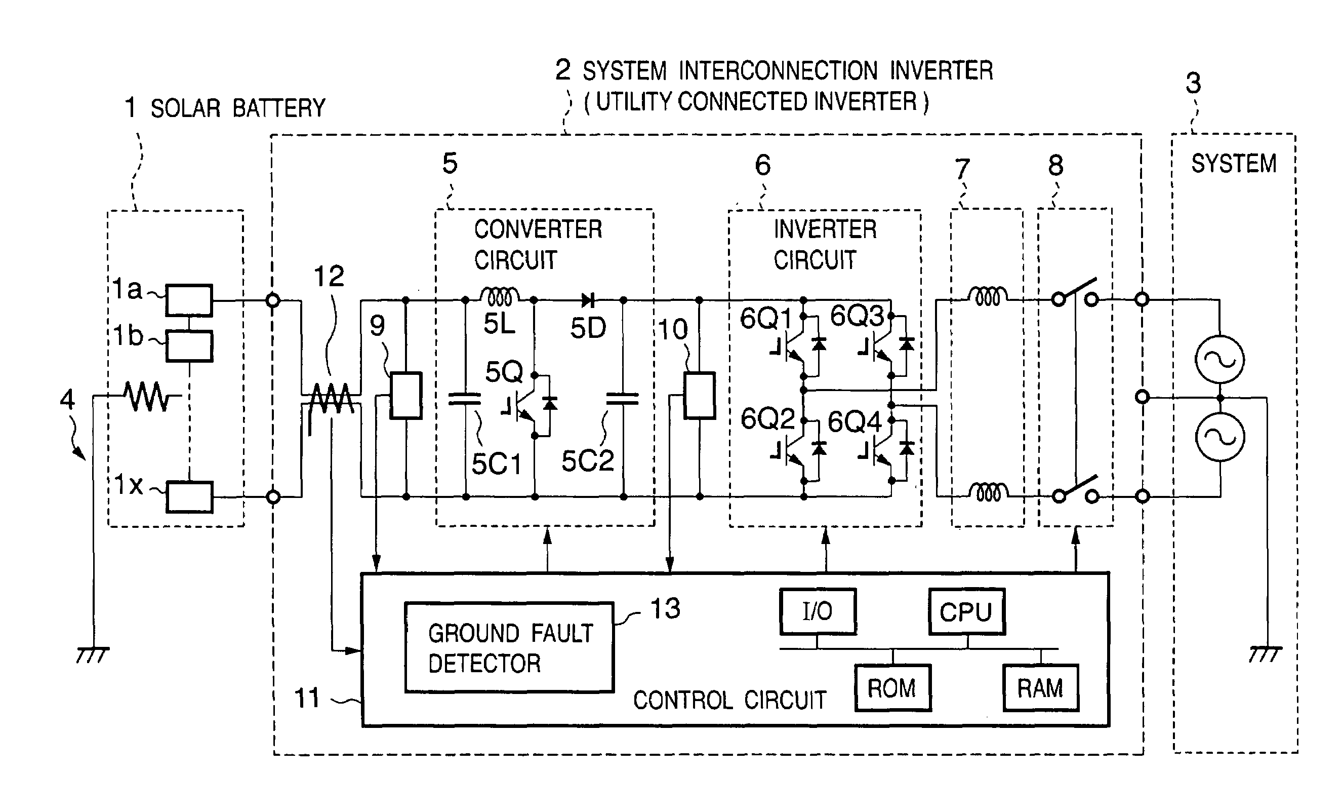
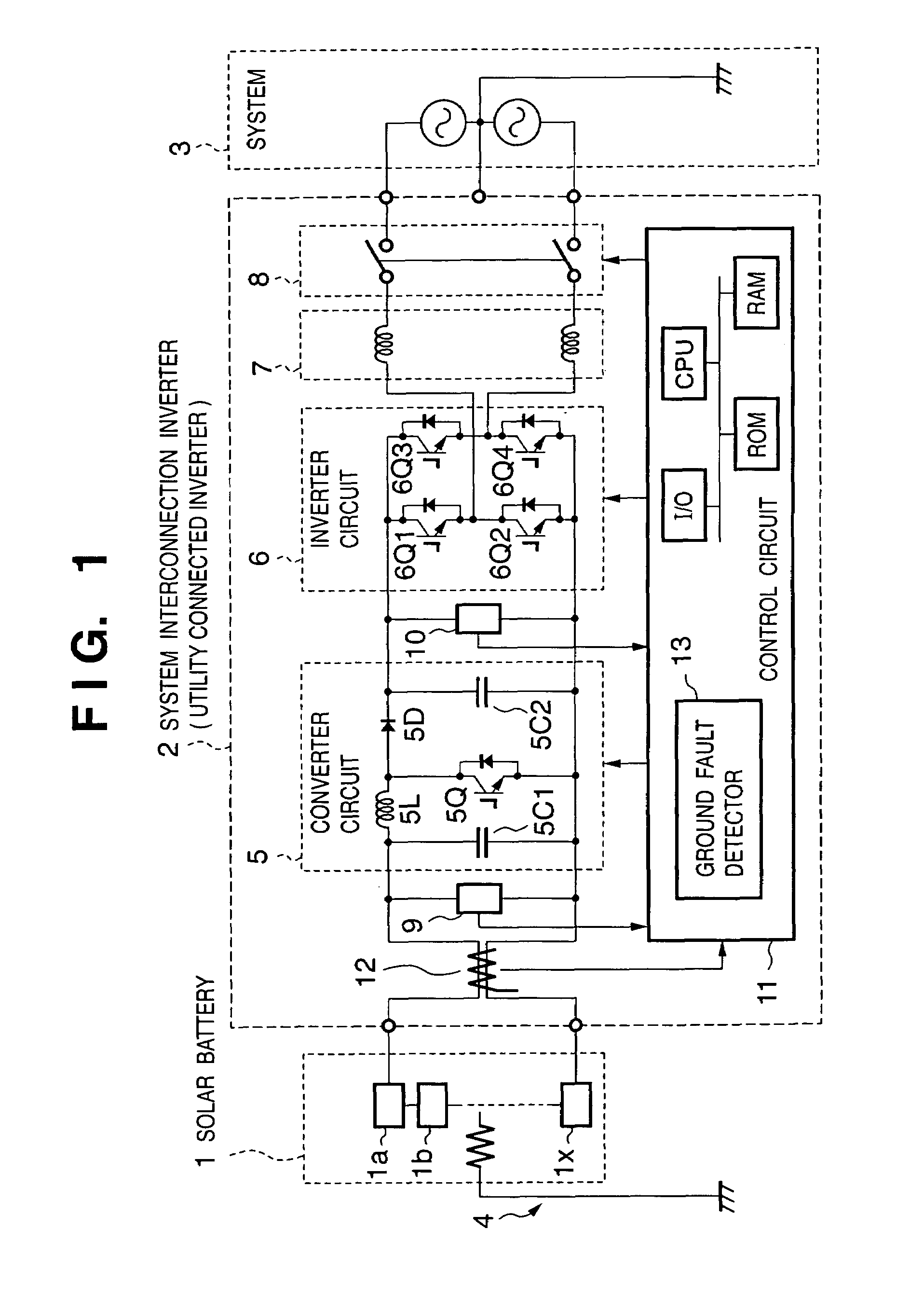
[0041]Ground fault detection operation in a system interconnection inverter (an utility connected inverter) 2 according to the first embodiment will be described next. The system interconnection inverter 2 has the same arrangement as in FIG. 1. In the first embodiment, an intermediate voltage Vm is kept constant, and only an input voltage Vi is changed.

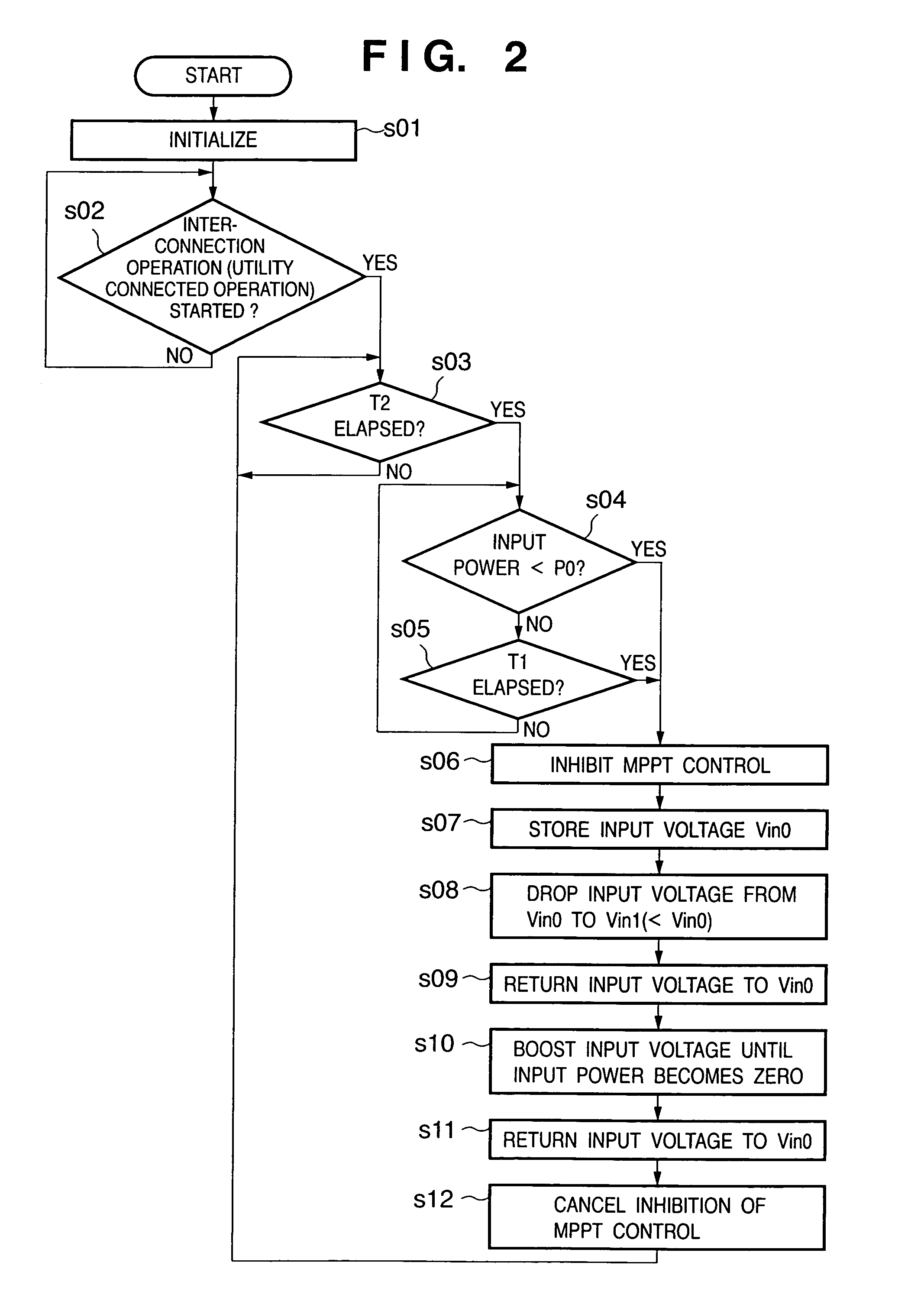
[0042]FIG. 2 is a flow chart showing voltage control in the ground fault detection operation. The voltage control is executed by a control circuit 11. When the control circuit 11 starts operating, various initialization operations are executed in step s01, as shown in FIG. 2. The control waits until interconnection operation (utility connected operation) starts in step s02. If YES in step s02, the flow advances to step s03.

[0043]It is determined in step s03 whether the time (to be referred to as an “operation time”) from the start of interconnection operation exceeds a second predetermined time T2. If YES in step s03, the flow advance...

second embodiment

[0070]The second embodiment will be described next. The system interconnection inverter (the utility connected inverter) of the second embodiment has the arrangement of a system interconnection inverter (an utility connected inverter) 2 shown in FIG. 1, as in the first embodiment. In the first embodiment, the input voltage is controlled to control the potential to ground. In the second embodiment, not only the input voltage but also the intermediate voltage is controlled.

[0071]FIG. 7 is a graph showing a variation in potential to ground of a solar battery 1 when both the input voltage and the intermediate voltage are controlled, in which the abscissa represents time, and the ordinate represents the potential to ground of the solar battery 1, as in FIG. 4. Normal operation continues until time t10. During this period, the potential to ground of the positive line of the solar battery 1 is VA0, and that of the negative line of the solar battery 1 is VB0.

[0072]Control to vary the potent...

third embodiment

[0085]The third embodiment will be described next. The system interconnection inverter (utility connected inverter) of the third embodiment has the arrangement of a system interconnection inverter (an utility connected inverter) 2 shown in FIG. 1, as in the first embodiment. The potential to ground is controlled by controlling the input voltage, as shown in FIG. 4 of the first embodiment. The distribution of potentials to ground in a solar battery 1 is the same as in FIG. 5. The third embodiment is different from the first embodiment in that a ground fault detector 13 has two ground fault detection levels.

[0086]FIG. 9 is a graph showing the boundaries of detectable ground fault resistance values that are obtained from the values shown in FIG. 5 and the ground fault detection levels (25 mA and 20 mA) of the ground fault detector 13. The abscissa represents a position x in the solar battery 1, and the ordinate represents the resistance value between the position x and the ground poten...


PUM


Abstract

The object is to reliably detect a ground fault of a solar battery. To detect a ground fault position to take an efficient measure against the ground fault, DC power input from a solar battery is converted into AC power and supplied to a system. In a system interconnection inverter (utility connected inverter) having non-insulated input and output, the input voltage of a converter circuit and/or the intermediate voltage between the converter circuit and an inverter circuit are varied to control the potential to ground at each portion of the solar battery to a value other than a value close to zero.

Description

FIELD OF THE INVENTION[0001]The present invention relates to a power converting apparatus, control method therefor, and solar power generation apparatus and, more particularly, to an inverter which receives power output from a DC power supply and outputs AC power to a commercial power system (electric utility) having a line grounded.BACKGROUND OF THE INVENTION[0002]In recent years, research and development of new clean energies have been encouraged along with buildup of environmental awareness, and solar power generation systems using solar batteries for directly converting the optical energy of the sun into an electrical energy are proliferating. Especially, system interconnection solar power generation systems (utility connected PV systems) in which DC power generated by a solar battery is converted into AC power by an inverter and output to a commercial power system are making a great market. The commercial power system (electric utility) will be simply referred to as a “system”,...

Claims


Application Information

Patent Timeline
Patent Type & Authority Patents(United States)
IPC IPC(8): H02H7/122G05F1/67H02J3/38H02J7/35H02M7/48H02M7/5387
CPCH02J7/0052H02J7/35H02J3/383H02M1/32H02J2007/0037H02J2007/004H02J2007/0059H02M2001/007Y02E10/563Y02E10/566Y10S323/906H02J7/00302H02J2207/20H02J7/00306H02J2300/24H02J3/381Y02E10/56H02M1/007H02J7/00
Inventor KUROKAMI, SEIJIMANABE, NAOKITAKEHARA, NOBUYOSHI
Owner CANON KK
Why Eureka
Try Eureka