Respiratory gas humidifier

a gas humidifier and respiratory illness technology, applied in lighting and heating apparatus, heating types, applications, etc., can solve the problems of affecting the efficiency of air purification, so as to facilitate the upgrading of gas humidifiers and efficient humidification

Active Publication Date: 2016-03-03
FISHER & PAYKEL HEALTHCARE LTD
View PDF2 Cites 11 Cited by
  • Summary
  • Abstract
  • Description
  • Claims
  • Application Information

AI Technical Summary

Benefits of technology

[0007]Certain features, aspects and advantages of at least one of the configurations disclosed herein include the realization that a gas channel in a gas humidifier can be shaped such that the forces created by gases moving through the gas channel can be used to draw water from a water reservoir to the gas channel. Advantageously, by heating the water in the gas channel, efficient humidification can be achieved. Additionally, certain features, aspects and advantages of at least one of the configurations disclosed herein include the realization that the gas channel can be detachably connected to the other components of the gas humidifier. Advantageously, the modularity of the gas humidifier can aid in the cleaning or sterilization of the gas humidifier and / or facilitate upgrading of the gas humidifier.

Problems solved by technology

A patient suffering from a respiratory illness can have difficulty engaging in effective respiration.
Conventional gas humidifiers are useful in ameliorating the discomfort of cold and dry gas therapies but it can take up to half an hour from turning the humidifier on to begin generating enough water vapor.
Additionally, conventional gas humidifiers may not be able to respond appropriately to changing input conditions or may have an impaired response in part due to the high thermal inertia of the water in the reservoir.

Method used


Image

  • Respiratory gas humidifier
  • Respiratory gas humidifier
  • Respiratory gas humidifier

Examples


Embodiment Construction

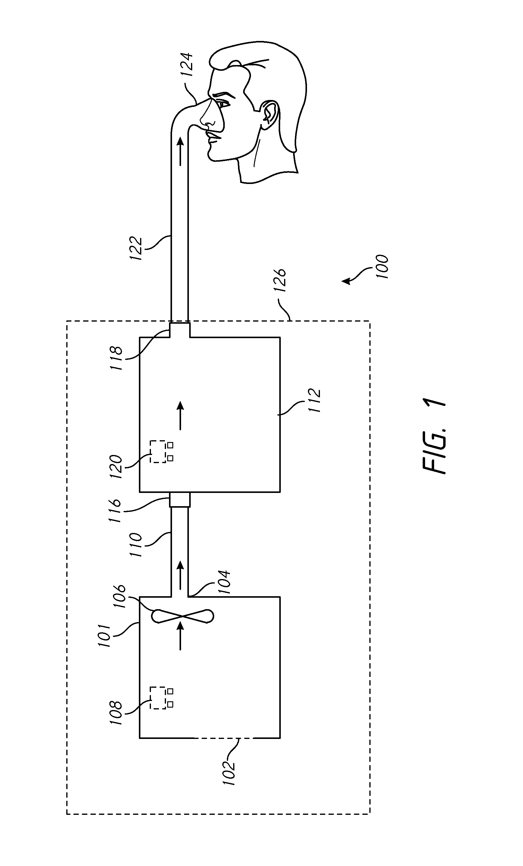
[0025]With reference to FIG. 1, a configuration for a respiratory therapy system 100 is shown. In the illustrated configuration, the respiratory therapy system 100 may comprise a flow generator 101. The flow generator 101 may comprise a gas inlet 102 and a gas outlet 104. The flow generator 101 may comprise a blower 106. The blower 106 may comprise a motor. The motor may comprise a stator and a rotor. The rotor may comprise a shaft. An impeller may be linked to the shaft. In use, the impeller may rotate concurrently with the shaft to draw in gas from the gas inlet 102. The flow generator 101 may comprise a user interface 108 which may comprise one or more buttons, knobs, dials, switches, levers, touch screens, speakers, displays, and / or other input or output modules that a user might use to view data and / or to input commands into the flow generator 101 to control its operation and / or the operation of other components of the respiratory therapy system 100. The flow generator 101 may ...


PUM

PropertyMeasurementUnit
volumeaaaaaaaaaa
velocityaaaaaaaaaa
pressureaaaaaaaaaa

Abstract

A gas humidifier can have a gas channel comprising an inlet and an outlet. A portion of the gas channel can have a region having a reduction in cross-sectional area relative to the portions of the gas channel outside of the region. A water conduit can extend from the region to a water reservoir. A heating element can heat water entering the region from the water conduit. Water vaporized using the heating element can join the flow of gases passing through the gas channel in use.

Description

INCORPORATION BY REFERENCE TO ANY PRIORITY APPLICATIONS[0001]Any and all applications for which a foreign or domestic priority claim is identified in the Application Data Sheet as filed with the present application are hereby incorporated by reference under 37 CFR 1.57. This application claims the priority benefit of U.S. Provisional Application Nos. 62 / 045460, filed Sep. 3, 2014 the entirety of which is hereby incorporated by reference herein and should be considered part of this specification.BACKGROUND[0002]1. Technical Field[0003]The present disclosure generally relates to respiratory gas therapy. More particularly, the present disclosure relates to gas humidification devices for use with respiratory gas therapy systems.[0004]2. Description of the Related Art[0005]A patient suffering from a respiratory illness can have difficulty engaging in effective respiration. In some cases, it is useful to provide the patient with a therapy that can improve the ventilation of the patient. I...

Claims


Application Information

Patent Timeline
Patent Type & Authority Applications(United States)
IPC IPC(8): A61M16/16A61M16/10
CPCA61M16/16A61M2205/36A61M16/1095A61M16/1085A61M2016/0027A61M2016/0039A61M2205/3368A61M2205/3653A61M2205/8206A61M2230/04A61M2230/10A61M2230/201A61M2230/202A61M2230/432A61M2230/435A61M16/109A61M16/161A61M16/202A61M16/024F24F3/14B01F23/21B01F35/90B01F2035/99B01F2101/55A61M16/0066A61M16/0808A61M16/0875A61M2016/003A61M2230/205
Inventor YATSEVICH, IGOR, OLEGOVICHPARTINGTON, ANDREW, JOHNALAMI, NORDYN
Owner FISHER & PAYKEL HEALTHCARE LTD
Why Eureka
Try Eureka