Tobacco processing machine

a technology for processing machines and tobacco, which is applied in the field of machines for processing tobacco bales or slices, can solve the problems of difficult control of the behavior of the temperature curve along the axis of the cylinder, scarcely effective humidification and/or heating of the intermediate product, and difficult control of the temperature curve. , to achieve the effect of scarcely effective equalization of temperature behavior

Inactive Publication Date: 2006-01-24
GARBUIO
View PDF17 Cites 1 Cited by
  • Summary
  • Abstract
  • Description
  • Claims
  • Application Information

AI Technical Summary

Benefits of technology

[0038]The aim of the present invention is to solve the above-described drawbacks by providing a tobacco processing machine that allows optimum treatment of the tobacco regardless of its density or lightness.
[0039]Within this aim, an object of the present invention is to provide a tobacco processing machine that allows to perform optimum humidification and / or effective heating of the intermediate product uniformly along the entire length of the cylindrical frame.
[0041]Another important advantage is the possibility to differentiate the amount of steam or water injected in the different parts of the length of the cylinder, so as to control the shape of the temperature curve and divide the cylinder into a plurality of regions.
[0042]A further object is to provide an optimum injection of the steam along the falling stream of tobacco, with a consequent substantial improvement of the efficiency of the machine.
[0043]A further object is to simplify and speed up the cleaning process at the end of the production cycle.
[0044]A further object is to provide a tobacco processing machine that is structurally simple and reliable and has low manufacturing costs.

Problems solved by technology

The main drawback of these conventional tobacco processing machines 1 is that the direct conditioning systems with which they are equipped, described briefly above, often perform a scarcely effective humidification and / or heating of the intermediate product 3.
In particular, it is very difficult to control the behavior of the temperature curve along the axis of the cylinder: the injection of the steam, which it the primary cause of the heating of the tobacco, causes only at the ends of the drum-like frame a heating that is characterized by two temperature peaks located at the input and output of the cylinder and by a central trough that covers most of the length of said cylinder.
The current of optionally preheated air, which should convey steam and water along the entire extension of the cylinder, is in practice scarcely effective in equalizing the temperature behavior.
Moreover, it worsens the drawback constituted by the difficulties in controlling the transit time of the tobacco inside the machine, since it acts differently depending on the characteristics of the tobacco being treated.
Another drawback consists in that the weight and consistency of the tobacco in transit cause a variation in the transit speed also as a function of the number and arrangement of the nozzles 6 for the injection of the steam and water from the ends of the frame.
Some conventional machines 1 can be equipped with mechanical means adapted to adjust the transit speed according to the quality and characteristics of the tobacco; however, such mechanical means are highly ineffective, since they assume a control of the rotation rate or inclination of the cylinder.
Moreover, the range available for varying the speed of the cylinder is very limited, since in order to properly form the falling stream 5 the product must fall from a rather narrow region of the upper end of the cylinder, designated by the angle α in FIG. 2.
One drawback of conventional machine 11 is the fact that it is often difficult to insert one or more tubes 13, which are necessary of the self-supporting type, along the entire length of the frame 14, which can in some cases exceed ten meters.
Another severe problem can be due to the continuous impact between the tobacco slices or bales and the tubes 13, which can lead to an excessive mechanical stress of said tubes and therefore to consequent malfunctions or breakdowns of said machine 11.
A further drawback of the conventional machines 11 is that leaves or strips of tobacco, designated by the reference numeral 19 in FIG. 4, can straddle said one or more tubes 13 and remain there until they are removed by chance by additional incoming intermediate product 16 or until the machine is cleaned at the end of the production cycle.

Method used


Image

  • Tobacco processing machine
  • Tobacco processing machine
  • Tobacco processing machine

Examples


Embodiment Construction

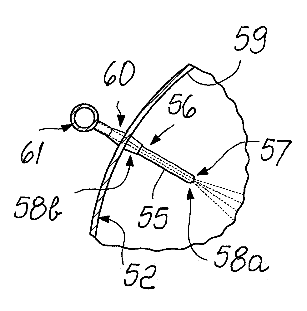
[0051]With reference to the figures, the reference numeral 51 designates a machine for processing tobacco bales or slices, advantageously constituted by a frame 52, which is advantageously cylindrical, conveniently hollow and arranged so that its axis is slightly inclined.

[0052]The frame 52 has, at its free ends, a tobacco input region 53a and an output region 53b for a intermediate product, which is designated by the reference numeral 54 in FIG. 6; in particular, the frame 52 is inclined so that the output region 53b is located at a lower level than the input region 53a.

[0053]The frame 52 rotates about its own axis so as to allow the intermediate product 54 to move toward the output region 53b.

[0054]During its rotation, the frame 52 also breaks up the tobacco bales or slices, advantageously through suitable movement means, which in this particular embodiment are constituted by multiple rods 55 that protrude radially inside the frame 52.

[0055]The machine 51 further comprises humid...


PUM


Abstract

A tobacco processing machine, comprising a frame that is cylindrical and hollow and has an inclined axis; the frame rotates axially so as to break up tobacco bales or slices and is internally provided with rods for moving the tobacco that protrude radially; the tobacco processing machine further comprising elements for feeding steam and / or water and / or another fluid, which are provided on the inner lateral surface of the frame.

Description

BACKGROUND OF THE INVENTION[0001]The present invention relates to a machine for processing tobacco bales or slices.[0002]Currently, in lines for processing tobacco at the manufacturing level, raw tobacco bales are broken up by means of a process that is commonly known as slicing and direct conditioning process.[0003]The tobacco bales, once freed from their packaging, depending on their dimensions may be subjected to slicing, so as to reduce them to dimensions that are compatible with the machines designed to process them.[0004]The tobacco slices or intact bales are then conveyed to a known type of machine, designated by the reference numeral 1 in FIGS. 1 and 2, which is conveniently constituted by a frame 2 that is shaped like a cylinder or a rotating drum.[0005]This known type of machine 1 for processing tobacco bales or slices must break them up, heat the resulting intermediate product, designated by the reference numeral 3, to the intended temperature, maintain its temperature fo...

Claims


Application Information

Patent Timeline
IPC IPC(8): A24B3/02A24B3/06A24B3/18
CPCA24B3/02A24B3/18A24B3/06
Inventor FAVARO, MANSUETO
Owner GARBUIO
Why Eureka
Try Eureka