Humidification device and air conditioner for vehicle

a technology for humidification devices and vehicles, applied in lighting and heating apparatus, transportation and packaging, heating types, etc., can solve the problems of inability to efficiently humidify the interior of the vehicle, limit the amount of water for replenishing the tank,

Inactive Publication Date: 2019-03-05
DENSO CORP
View PDF28 Cites 1 Cited by
  • Summary
  • Abstract
  • Description
  • Claims
  • Application Information

AI Technical Summary

Benefits of technology

[0007]Therefore, it is an object of the present disclosure to provide a humidification device and an air conditioner for a vehicle that can efficiently humidify the vehicle interior without being supplied with water from the outside.
[0015]With this arrangement, the moisture of the cooled air produced by the air-conditioning unit can be used to humidify the vehicle interior, and thereby there is no need for water to be supplied from the outside into the vehicle air conditioner. In particular, the first introduction portion that introduces the cooled air into the adsorption case is connected to the bottom surface portion of the air-conditioning case on the air-flow downstream side of the cooling portion in the air-conditioning case. Thus, the cooled air at a comparatively high relative humidity inside the air-conditioning case is introduced into the adsorption case, so that the adsorption amount of moisture into the adsorbent can be sufficiently ensured.
[0016]Therefore, the present disclosure can efficiently humidify the vehicle interior without supplying any water from the outside into the vehicle air conditioner.
[0019]Thus, the first introduction portion is connected to the air-flow downstream side of the drain discharge portion in the air-conditioning unit, thereby making it possible to prevent the adsorbent from being covered with the condensed water generated in the cooling portion.

Problems solved by technology

However, in vehicles as a movable body, there is a limitation on the amount of water for replenishing the tank.
If the water in the tank and water for replenishing the tank cannot be ensured, the vehicle interior cannot be efficiently humidified.

Method used


Image

  • Humidification device and air conditioner for vehicle
  • Humidification device and air conditioner for vehicle
  • Humidification device and air conditioner for vehicle

Examples


first embodiment

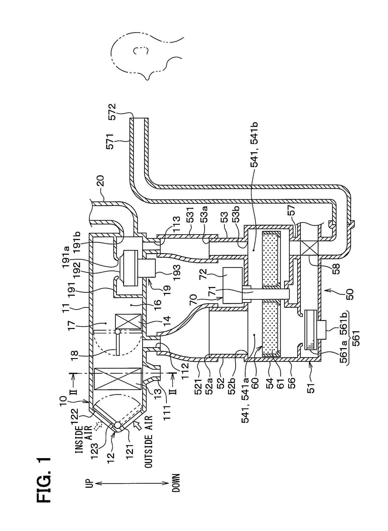
[0031]This embodiment will describe an example in which a vehicle air conditioner to perform air-conditioning of the vehicle interior is applied to a vehicle that obtains a driving force for vehicle traveling from an internal combustion engine (for example, engine) (not shown). As shown in FIG. 1, the vehicle air conditioner includes an air-conditioning unit 10 and a humidification device 50 as main components. Note that respective arrows indicating the upper and lower sides shown in FIG. 1 indicate the up and down directions when the vehicle air conditioner is mounted on the vehicle. The same goes for other drawings.

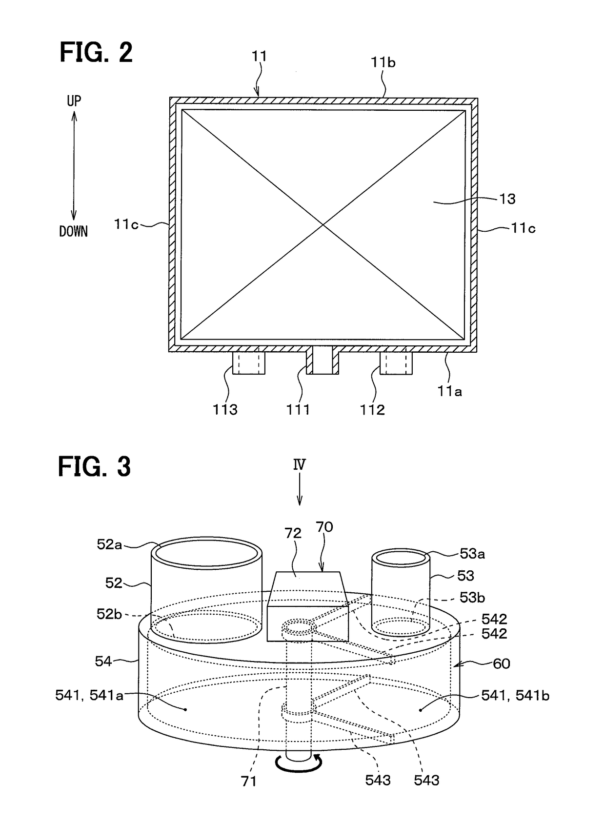
[0032]First, the air-conditioning unit 10 will be described. The air-conditioning unit 10 is disposed below a dashboard (i.e., an instrumental panel) in the vehicle interior. The air-conditioning unit 10 accommodates an evaporator 13 and a heater core 14 in an air-conditioning case 11 forming an outer shell of the air-conditioning unit.

[0033]The air-conditioning case 11...

second embodiment

[0134]Next, a second embodiment will be described with reference to FIG. 9.

[0135]This embodiment differs from the first embodiment in that the humidification device 50 is applied to an air-conditioning unit 10A in which an air-conditioning blower 19A is disposed on the air-flow upstream side of the evaporator 13. In this embodiment, the description of the same or equivalent parts or the like as those in the first embodiment will be omitted or simplified.

[0136]As shown in FIG. 9, in the air-conditioning unit 10A of this embodiment, the air-conditioning blower 19A is disposed on the air-flow downstream side of the inside / outside air switching box 12 and on the air-flow upstream side of the evaporator 13. In the air-conditioning blower 19A of this embodiment, the suction port 191a is opened toward the inside / outside air switching box 12, while the discharge port 191b is opened toward the evaporator 13.

[0137]A hot-air guiding portion 113A in this embodiment is formed on the air-flow dow...

third embodiment

[0148]Next, a third embodiment will be described with reference to FIG. 10. This embodiment differs from the first embodiment in that a discharge route for the air passing through the moisture-adsorption space 541a of the adsorption case 51 is modified. In this embodiment, the description of the same or equivalent parts or the like as those in the first embodiment will be omitted or simplified.

[0149]As shown in FIG. 10, in this embodiment, the air-conditioning case 11 is connected to an opening as the downstream-side end of a cold-air discharge duct 562 so as to allow the air having passed through the moisture-adsorption space 541a to be discharged toward the outside. In this embodiment, the cold-air discharge duct 562 is connected to the air-conditioning case 11 such that the air flowing through the cold-air discharge duct 562 is returned to the cold-air bypass passage 17. Note that a part of the connection of the cold-air discharge duct 562 is not limited thereto, and can be conne...


PUM


Abstract

A humidification device includes: an adsorber having an adsorbent that adsorbs and desorbs moisture; an adsorption case that forms an accommodating space to accommodate the adsorber; a first introduction portion that introduces cooled air produced by a cooling portion into the adsorption case; a second introduction portion that introduces heated air produced by the heating portion into the adsorption case; and a humidification-side guiding portion that guides humidification air humidified by the moisture desorbed within the adsorption case, to the vehicle interior. The first introduction portion is connected to a bottom surface portion of the air-conditioning case on the air-flow downstream side of the cooling portion in the air-conditioning case.

Description

CROSS REFERENCE TO RELATED APPLICATIONS[0001]This application is a U.S. National Phase Application under 35 U.S.C. 371 of International Application No. PCT / JP2016 / 055398 filed on Feb. 24, 2016 and published in Japanese as WO 2016 / 147819 A1 on Sep. 22, 2016. This application is based on and claims the benefit of priority from Japanese Patent Application No. 2015-056255 filed on Mar. 19, 2015. The entire disclosures of all of the above applications are incorporated herein by reference.FIELD OF THE INVENTION[0002]The present disclosure relates to a humidification device applied to an air-conditioning unit, and an air conditioner for a vehicle that includes an air-conditioning unit and a humidification device.BACKGROUND ART[0003]Conventionally, there is a known air-conditioning unit for a vehicle equipped with a humidifier that humidifies the vehicle interior (see, for example, Patent Document 1). Patent Document 1 discloses an air-conditioning unit that includes permeable tubes designe...

Claims


Application Information

Patent Timeline
Patent Type & Authority Patents(United States)
IPC IPC(8): B60H1/32B60H3/02F24F3/14
CPCB60H1/3201B60H3/022F24F3/1411F24F3/1423F24F3/14B60H2003/028
Inventor ITO, KOJINAKAMURA, TAKAHITOSAKAKIBARA, DAISUKEKATO, SHINYAYAMAOKA, JUN
Owner DENSO CORP
Why Eureka
Try Eureka