

Carrier system and method for controlling carrier system
a carrier system and carrier technology, applied in the direction of transportation and packaging, storage devices, etc., can solve the problems of disruption of the travel of another carrier that travels along the rail, and achieve the effect of rapid carrying of a cargo
- Summary
- Abstract
- Description
- Claims
- Application Information
AI Technical Summary
Benefits of technology
Problems solved by technology
Method used
Image

Examples
first embodiment
1-1. Whole Configuration of Carrier System
[0035]First, a whole configuration of a carrier system according to the first embodiment will be described with reference to FIGS. 1 and 2.
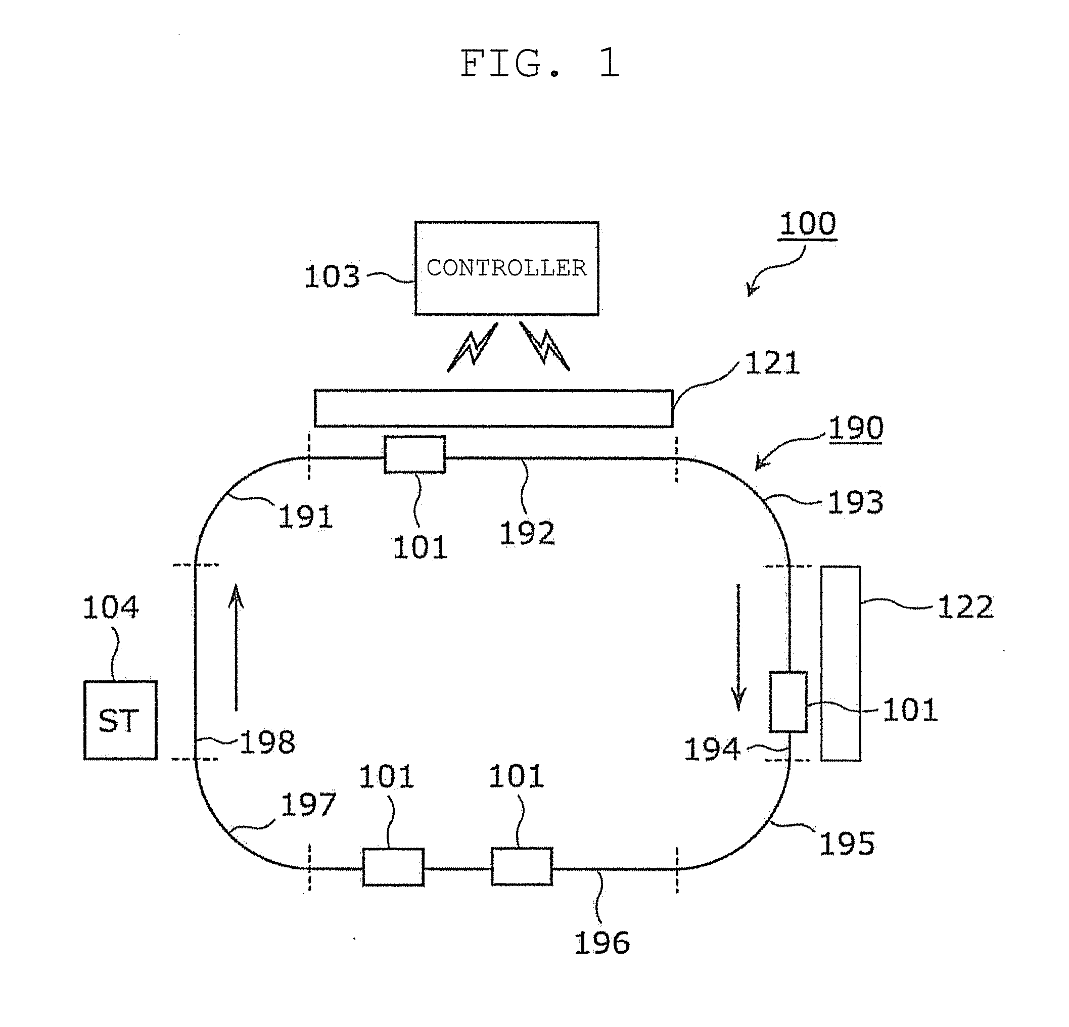
[0036]FIG. 1 is a plan view illustrating a configuration outline for a carrier system according to the present embodiment.
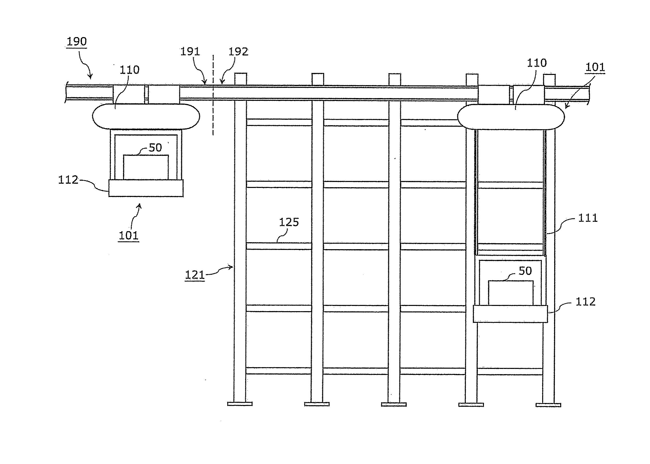
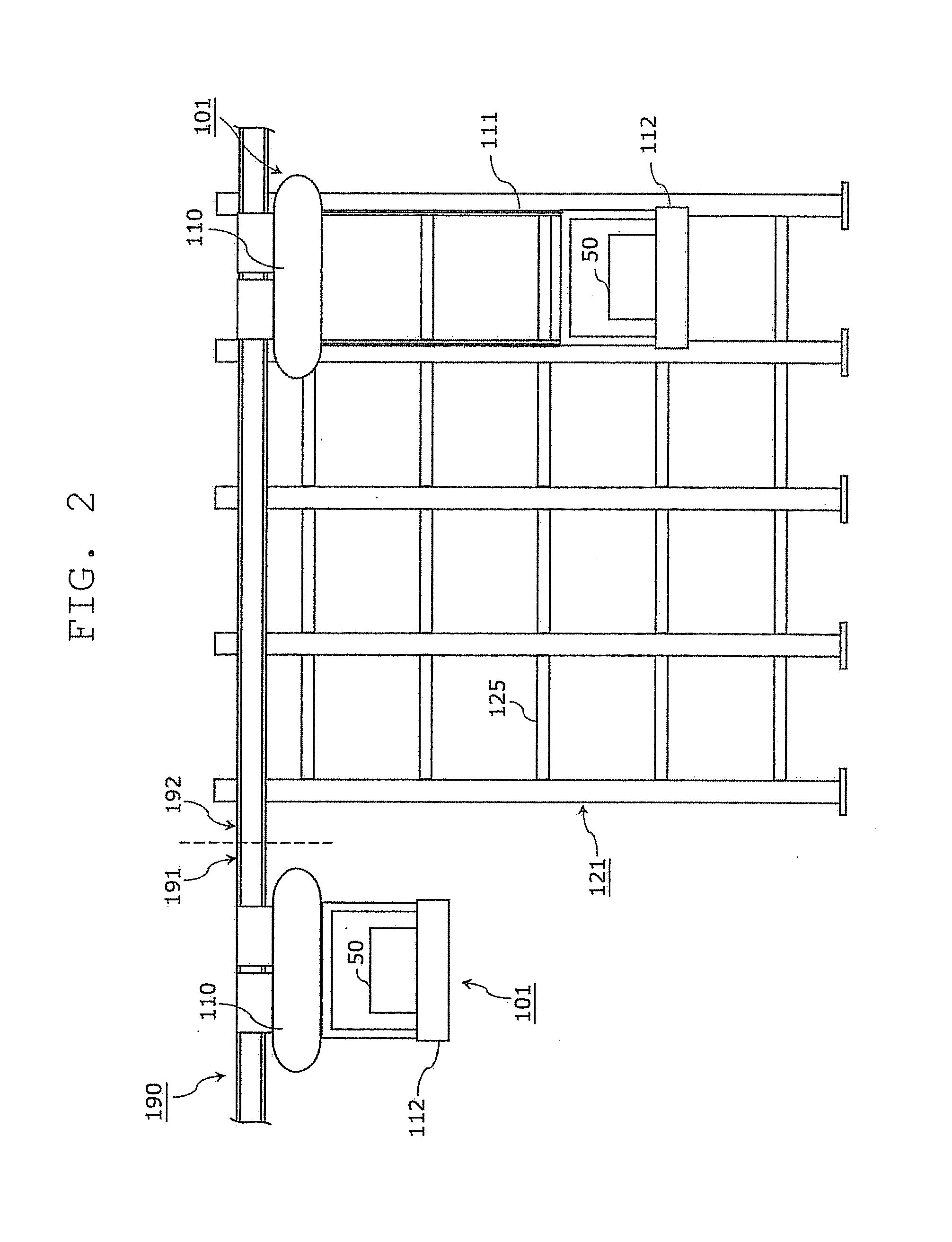
[0037]FIG. 2 is a front view illustrating a configuration outline for a carrier and a rack according to the present embodiment.
[0038]As illustrated in FIG. 1, a carrier system 100 according to the present embodiment includes a circulation rail 190, a plurality of carriers 101 that travel along the circulation rail 190, and a controller 103 that controls an operation of the carrier 101. Further, racks 121 and 122 and a station 104 are provided in positions along the circulation rail 190.
[0039]The circulation rail 190 is a structure hung from above and including a curved part. The circulation rail 190 guides travelling of the carrier 101 and forms a travelling route of the carrier 101. I...
second embodiment
[0087]Next, a carrier system according to a second embodiment will be described. In the carrier system 100 according to the first embodiment, the storing position of the cargo 50 has been preferentially selected from the priority placement parts. However, in the above first embodiment, since the frequency of storing and delivery (storing / delivery frequency) by the cargo 50 is not considered, for example, the cargo 50 with a low storing / delivery frequency may be placed on the priority placement part and the cargo 50 with a high storing / delivery frequency may be placed on the non-priority placement part. In this case, the cargo 50 with a high storing / delivery frequency located on the non-priority placement part is frequently stored and delivered, and in each time of the storing and delivery, the carrier 101 stops over a relatively long time. In the present embodiment, in order to suppress a harmful influence exerted by placement of the cargo 50 with a low storing / delivery frequency on...
third embodiment
[0101]Next, a carrier system according to a third embodiment will be described. In each of the above embodiments, there has been employed the configuration where the travelling vehicle 110 is made to travel in the state where the lift stage 112 of the carrier 101 has been lifted to the position in the vicinity of the travelling vehicle 110 in the curved part of the circulation rail 190. In the present embodiment, there is employed a configuration where the lift stage 112 is not necessarily lifted to the position in the vicinity of the travelling vehicle 110 in the curved part of the circulation rail 190, and the speed of the travelling vehicle 110 is changed in accordance with the lowering amount of the lift stage 112. Hereinafter, a description will be mainly given of a functional configuration and an operation of a carrier in the carrier system according to the present embodiment which are points of difference from each of the above embodiments.
3-1. Functional Configuration of Car...
PUM
 Abstract
Description
Claims
Application Information