Adaptive coding of a prediction error in hybrid video coding

a hybrid video and prediction error technology, applied in the field of coding and decoding, coders and decoders, and data signals using adaptive coding of prediction errors, can solve the problems of low only high coding efficiency of transforms, so as to reduce data rate, reduce temporal redundancy, and reduce the effect of redundancy

Active Publication Date: 2016-05-12
KONINKLJIJKE PHILIPS NV
View PDF0 Cites 0 Cited by
  • Summary
  • Abstract
  • Description
  • Claims
  • Application Information

AI Technical Summary

Benefits of technology

[0006]According to an aspect of the present invention, a method for coding a video signal is provided being based on hybrid coding. The method comprises the steps of reducing temporal redundancy by block based motion compensated prediction in order to establish a prediction error signal, and deciding whether to transform the prediction error signal into the frequency domain, or to maintain the prediction error signal in the spatial domain.
[0019]Further, according to still another aspect of the invention, the data signal may include side information indicating the domain in which a slice, a macroblock, or a block is coded, in particular information whether a slice, a macroblock or a block is coded in the spatial or in the frequency domain. As the adaptive control according to the present invention provides that the prediction error signal is either coded in the spatial domain or in the frequency domain, it is necessary to include corresponding information into the coded video signal. Therefore, the present invention provides also a specific information, which indicates the domain in which the specific portion, such as a slice, macroblock, or block has been coded. Further, this aspect of the invention takes also account of the possibility that a whole macroblock or a whole slice may be coded only in one of the two domains. So, if for example an entire macroblock is coded in the spatial domain, this may be indicated by a single flag or the like. Further, even a whole slice may be coded only in the frequency or in the spatial domain, and a corresponding indicator could be included for the whole slice into the data stream. This results in a decreased data rate and a more efficient coding mechanism for the side information.

Problems solved by technology

However, the coding efficiency of the transform only is high, if the prediction error samples are correlated.
For samples being only marginally correlated in the spatial domain, the transform is less efficient.

Method used


Image

  • Adaptive coding of a prediction error in hybrid video coding
  • Adaptive coding of a prediction error in hybrid video coding
  • Adaptive coding of a prediction error in hybrid video coding

Examples


Embodiment Construction

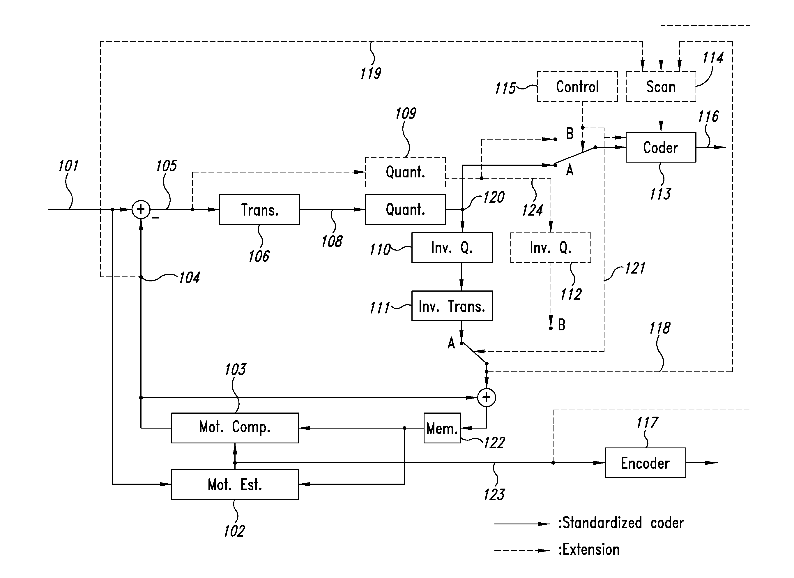
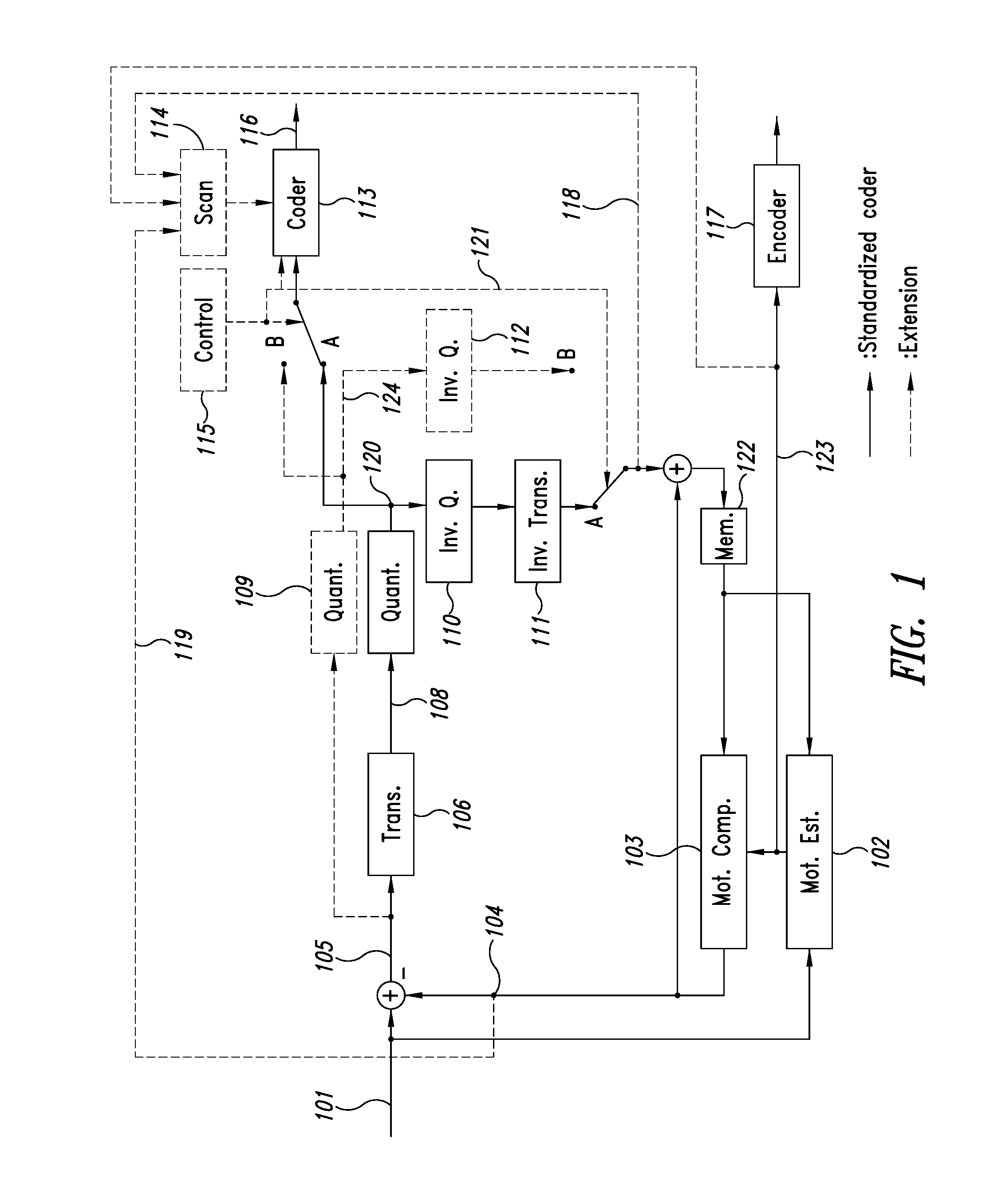
[0027]FIG. 1 shows a simplified block diagram of an encoder according to the present invention. Accordingly, the input signal 101 undergoes a motion estimation based on which a motion compensation prediction is carried out in order to provide a prediction signal 104, which is subtracted from the input signal 101. The resulting prediction error signal 105 is transformed into the frequency domain 106 and quantised by an optimised quantiser 107 for the frequency related coefficients. The output signal 120 of the quantiser 107 is passed to an entropy coder 113 which provides the output signal 116 to be transmitted, stored, or the like. By means of an inverse quantisation block 110 and inverse transformation block 111, the quantised prediction error signal 120 is further used for the next prediction step in the motion compensated prediction block 103. The inverse quantised an inverse DCT transformed prediction error signal is added to the prediction signal and passed to frame memory 122 ...


PUM


Abstract

The present invention relates to a method for coding a video signal using hybrid coding, comprising: reducing temporal redundancy by block based motion compensated prediction in order to establish a prediction error signal, deciding whether to transform the prediction error signal into the frequency domain, or to maintain the prediction error signal in the spatial domain for encoding.

Description

BACKGROUND[0001]1. Technical Field[0002]The invention relates to a method of coding and decoding, a coder and a decoder, and data signals using adaptive coding of the prediction error.[0003]2. Description of the Related Art[0004]Up to date standardized video coding methods are based on hybrid coding. Hybrid coding provides a coding step in the time domain and a coding step in the spatial domain. First, the temporal redundancy of video signals is reduced by using a block based motion compensated prediction between the image block to be coded and a reference block from an image that has already been transmitted determined by a motion vector. The remaining prediction error samples are arranged in blocks and are transformed into the frequency domain resulting in a block of coefficients. These coefficients are quantised and scanned according to a fixed and well-known zigzag scanning scheme, which starts with the coefficient representing the DC value. According to a typical representation...

Claims


Application Information

Patent Timeline
Patent Type & Authority Applications(United States)
IPC IPC(8): H04N19/65H04N19/61H04N19/167H04N19/126H04N19/176H04N19/44H04N19/52H04N19/43H04N19/89
CPCH04N19/65H04N19/52H04N19/61H04N19/167H04N19/126H04N19/176H04N19/44H04N19/43H04N19/147H04N19/46H04N19/13H04N19/129H04N19/12H04N19/124H04N19/70H04N19/103H04N19/51H04N19/19
Inventor NARROSCHKE, MATTHIASMUSMANN, HANS-GEORG
Owner KONINKLJIJKE PHILIPS NV
Why Eureka
Try Eureka