Ultrasonic Flow Meter

a flow meter and ultrasonic technology, applied in the direction of volume/mass flow measurement, measurement devices, instruments, etc., can solve the problem of accurate transit time, achieve accurate measurement of absolute transit time, reduce temporal uncertainty, and improve accuracy

Active Publication Date: 2016-07-07
APATOR MIITORS APS
View PDF9 Cites 16 Cited by
  • Summary
  • Abstract
  • Description
  • Claims
  • Application Information

AI Technical Summary

Benefits of technology

[0012]One advantage of the invention may be that a more accurate measurement of the absolute transit times may be obtained. As a result of the temporal uncertainty being lowered, a more accurate measurement of the flow through the flow tube may be obtained.
[0013]Surprisingly, it has been discovered by the inventors of the present invention that some reflector materials may be significantly advantageous compared to materials, which are normally used, such as stainless steel. Typically, it may be the goal to maximize the difference between the acoustic impedance of the reflector material and the fluid. Typically, many fluids have an acoustic impedance lower that metals used as reflectors. Therefore, typically, materials with a high acoustic impedance are chosen. Since environmental and health concerns often restrict the choice of materials, it is generally established within the art to use stainless steel reflectors.
[0014]However, it has surprisingly been discovered by the inventors that by using reflectors of materials comprising large amounts of copper in amounts of at least 50% by weight, hereunder e.g. many brass materials, an improved accuracy of the flow measurement may be obtained. Studies show that this may be a result of the fact that ultrasound signal may often excite certain acoustic surface modes in the ultrasound reflectors, which may lead to distortion and / or noise being introduced into the signal, thereby lowering the accuracy of the measurement of the transit time, and, ultimately, to a lowering of the accuracy of the measurement of the fluid flow. However, by using reflectors according to the invention, the inventors were able to significantly reduce the induced distortion and measure the transit time, and, consequently, the fluid flow, more accurately.
[0017]transmitting a second ultrasound signal from said second ultrasound transducer and detecting said second ultrasound signal by said first ultrasound transducer,
[0018]In more detail and further to the above described advantage, establishing both absolute transit times and difference between such transit time from the same measured signals with great precision may often prove difficult, if not impossible, since measuring absolute transit time with great precision would typically require very short ultrasound signals, such as single pulse signals, while measuring difference time between the transit times with great precision may often require long signals comprising several pulses, such as at least 8 pulses, or even more. However, the inventors of the present invention have surprisingly found that by using ultrasound reflectors according to the invention, this may be achieved.
[0019]One advantage of the invention may be that the velocity of the ultrasound in the reflectors is reduced, thereby reducing the coupling of energy into disadvantageous surface vibrational modes, which may induce distortion into the ultrasound signal. Thereby, it may be possible to obtain flow measurements with a relatively high accuracy.

Problems solved by technology

One problem related to such meters may be measuring the transit time accurately.

Method used


Image

  • Ultrasonic Flow Meter
  • Ultrasonic Flow Meter
  • Ultrasonic Flow Meter

Examples


Embodiment Construction

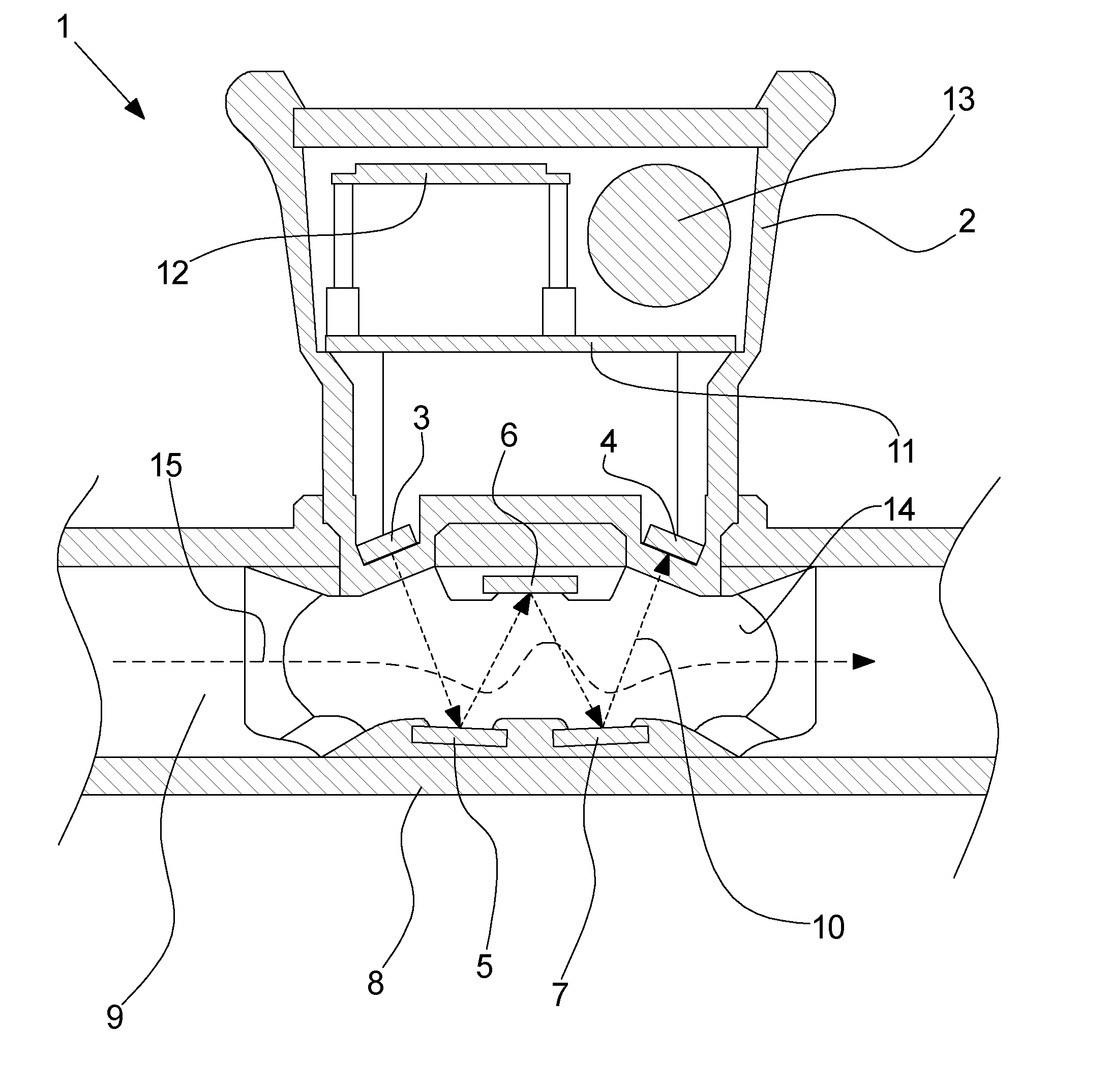
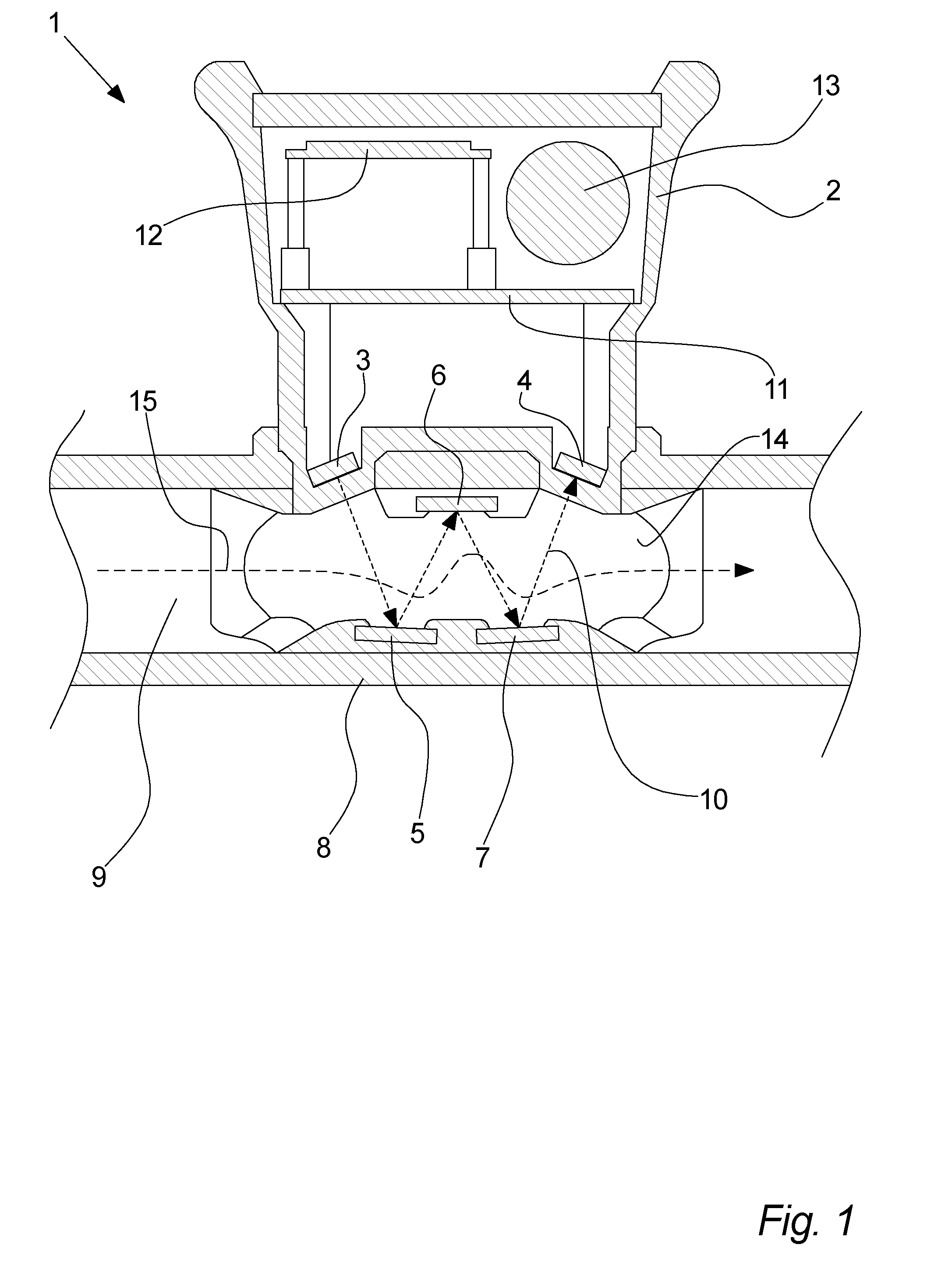
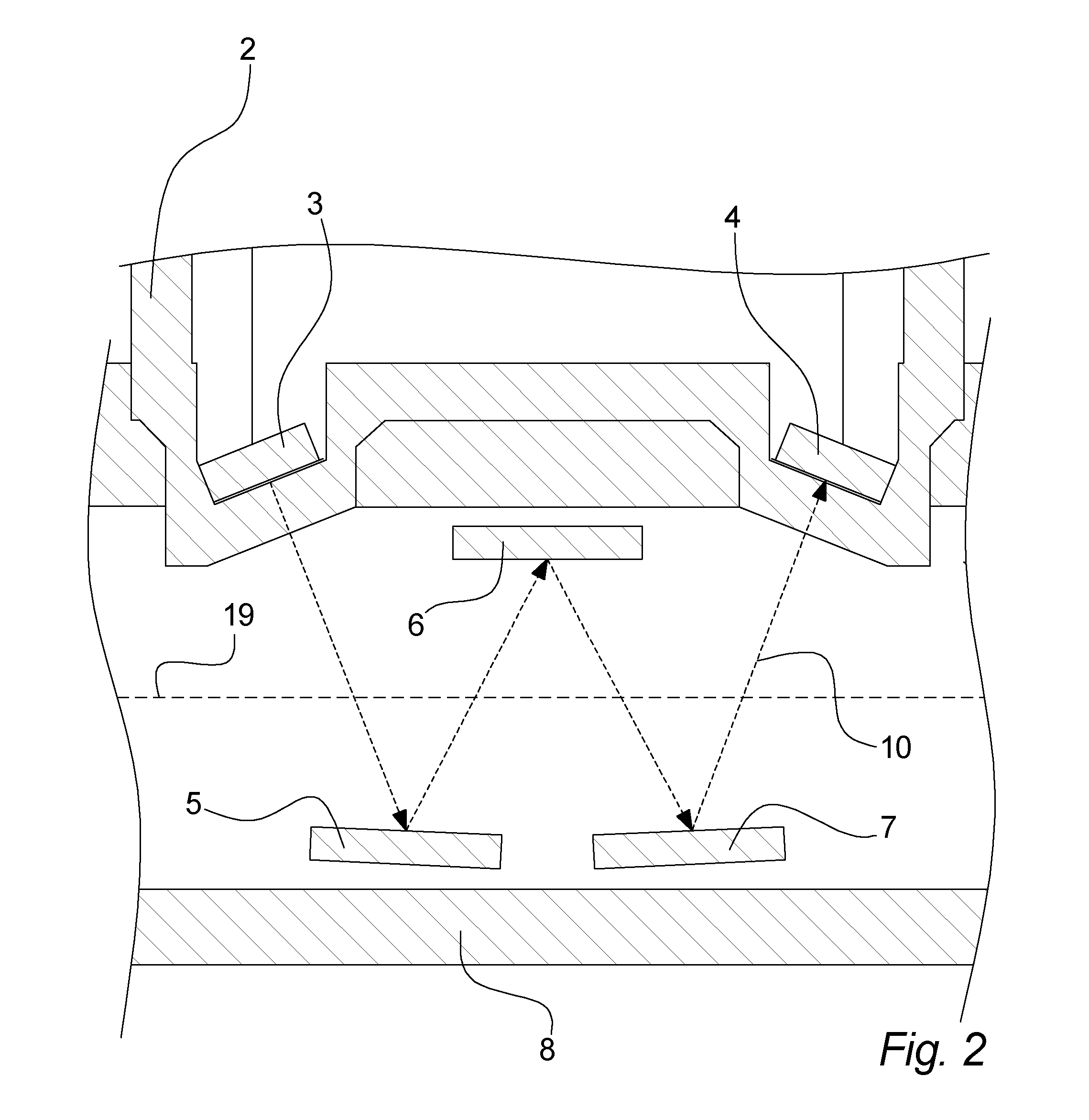
[0154]According to an embodiment, the flow of a fluid may be determined in an ultrasonic flow meters 1 by calculating it from a first transit time t1 from the first ultrasound transducer 3 to the second ultrasound transducer 4 and a second transit time t2 from the second ultrasound transducer 4 to the first ultrasound transducer 3. Specifically, the following formula may be used to calculate a fluid flow Φ

Φ∝K(t1-t2,t1+t2)·t1-t2t1+t2(Equation1)

[0155]where K(t1−t2, t1+t2) is a correction factor, which may typically be determined once and for all for a given meter and a given fluid. The correction factor may correct for such factors as e.g. dimensions and physical configuration of the fluid flow path 15, and the viscosity of the fluid to be measured.

[0156]As can be seen from Equation 1, once the table of correction factors has been established, the flow indication can be calculated from the two quantities (t1−t2) and (t1+t2).

[0157]The first of these quantities, (t1−t2), which is the di...


PUM


Abstract

An ultrasonic flow meter is disclosed, the ultrasonic flow meter including a flow tube with a flow channel for a fluid to be measured, and two ultrasound reflectors fixated inside the flow tube, a first ultrasound transducer, a second ultrasound transducer, and an electronic control arrangement for operating the ultrasonic flow meter. The ultrasound transducers and reflectors have relative positions and orientations forming an ultrasound path from the first ultrasound transducer to the at least two ultrasound reflectors, to the second ultrasound transducer, and vice versa. The ultrasonic flow meter measures absolute transit times of the ultrasound signal from the first ultrasound transducer to the second ultrasound transducer, and/or vice versa, and the ultrasound reflectors include at least 50% by weight of copper, and the ultrasound signal includes at least 8 pulses.

Description

FIELD OF THE INVENTION[0001]The invention relates to an ultrasonic flow meter according to claim 1.BACKGROUND OF THE INVENTION[0002]Several ultrasonic flow meters are known within the art. One example is may be seen in international patent application WO 2011 / 134470 A2.[0003]One problem related to such meters may be measuring the transit time accurately.[0004]It may therefore be an object of the invention to increase the accuracy of the transit time measurements.SUMMARY OF THE INVENTION[0005]The invention relates to an ultrasonic flow meter comprising[0006]a flow tube defining an flow channel for a fluid to be measured, and[0007]at least two ultrasound reflectors fixated inside said flow tube,[0008]a first ultrasound transducer,[0009]a second ultrasound transducer,[0010]an electronic control arrangement for operating said ultrasonic flow meter,said ultrasound transducers and reflectors having relative positions and orientations defining an ultrasound path from said first ultrasound ...

Claims


Application Information

Patent Timeline
Patent Type & Authority Applications(United States)
IPC IPC(8): G01F1/66
CPCG01F1/662G01F1/667
Inventor DRACHMANN, JENSCALDWELL, POL MARTINEZ
Owner APATOR MIITORS APS
Why Eureka
Try Eureka