Filament winding apparatus and method of controlling filament winding apparatus

Active Publication Date: 2016-09-15
TOYOTA JIDOSHA KK
View PDF0 Cites 8 Cited by
  • Summary
  • Abstract
  • Description
  • Claims
  • Application Information

AI Technical Summary

Benefits of technology

[0027]The roller guides the fibers impregnated with a thermosetting resin, while making the resin-impregnated fibers in contact with the roller. The suction hole of the roller is thus likely to be clogged by the thermosetting resin. In the filament winding apparatus of this aspect, the suction hole of the roller is the pores of the porous material. This configuration suppresses the suction hole from being clogged by the thermosetting resin.
[0028]The invention may be implemented by any of various aspects other than those described above. The invention may be implemented by, for example, a filament winding apparatus, a filament winding system, a high pressure tank manufacturing apparatus utilizing a filament winding method, a high pressure tank manuf

Problems solved by technology

In the case where the position of the fiber bundle on the roller is deviated from an adequate location, there is a likelihood that the high pressure tank is not formed in the designed configuration even when the filament winding apparatus drives the guide assembly and the liner to wind the fiber bundle according to a predetermined program.
In the case where the fiber bundle has no misalignment, the suction unit may not perform suction or may reduce the magnitude of the suction force.
In the case where the fiber bundle has a significant misalignment, on the other hand, the suction unit may perform suction or may increase the magnitude of the suction force.
The suction unit may not perform suction or may reduce the magnitude of the suction force with respect to the suction hole that does not corresponding to the location

Method used


Image

  • Filament winding apparatus and method of controlling filament winding apparatus
  • Filament winding apparatus and method of controlling filament winding apparatus
  • Filament winding apparatus and method of controlling filament winding apparatus

Examples


first embodiment

A. First Embodiment

A-1. Configuration of Filament Winding Apparatus

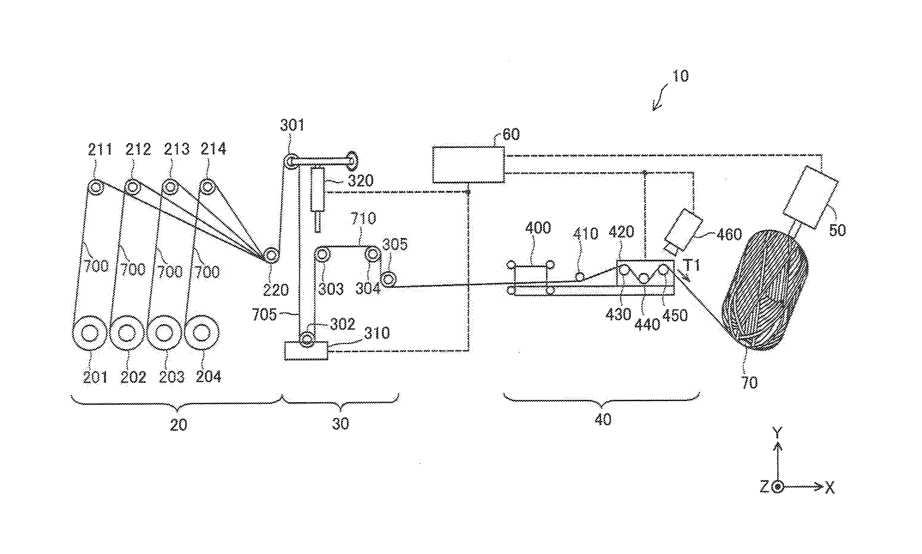
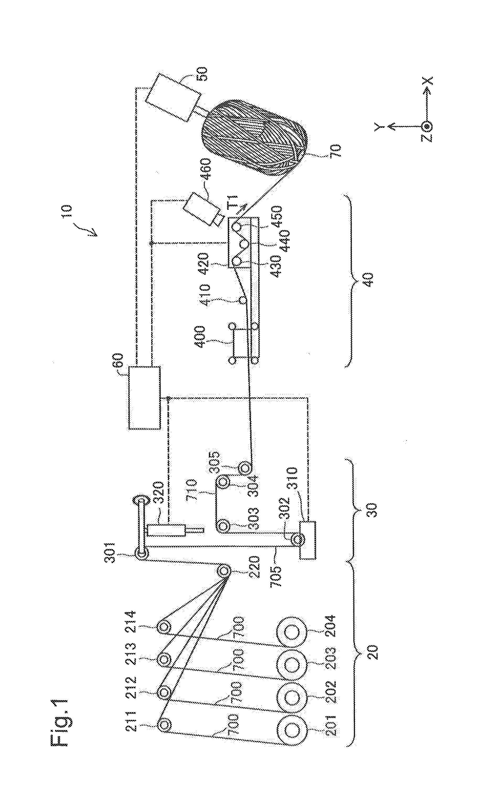
[0036]FIG. 1 is a diagram illustrating the configuration of a filament winding apparatus 10 according to one embodiment of the invention. The filament winding apparatus 10 is configured to wind a fiber bundle consisting of a plurality of fibers on a liner 70 that is the core of a high pressure tank in a method of manufacturing the high pressure tank by filament winding method. The description of FIG. 1 and subsequent drawings is on the assumption that the conveying direction of the fiber bundle is X-axis direction, the height direction is Y-axis direction and the width direction of various rollers to convey fibers is Z-axis direction.

[0037]The filament winding apparatus 10 includes a fiber feeder 20, a resin impregnation assembly 30, a guide assembly 40, a liner rotating device 50 and a controller 60. In the filament winding apparatus 10 of this embodiment, rollers of the guide assembly 40 are configured as described...

second embodiment

B. Second Embodiment

[0071]A second embodiment of the invention describes a configuration that detects misalignment of a fiber bundle or the like and performs feedback control. The configuration and the procedure similar to those of the first embodiment are expressed by the like signs to those of the first embodiment described above, and their detailed descriptions are omitted. In other words, the configuration and the procedure that are not described below are similar to those of the first embodiment described above.

B-1. Configuration of Filament Winding Apparatus

[0072]A filament winding apparatus 10 according to the second embodiment has configuration substantially similar to that of the first embodiment shown in FIG. 1. The filament winding apparatus 10 of the second embodiment, however, differs from the first embodiment shown in FIG. 1 by that the filament winding apparatus 10 of the second embodiment has a position adjuster 420a in place of the position adjuster 420 and the cont...

modification 1

[0091]The above embodiment illustrates one example of the configuration of the filament winding apparatus. The configuration of the filament winding apparatus may, however, be changed or modified in any of various ways. For example, some components may be added, deleted or exchanged.

[0092]According to one modification, a prepreg impregnated with a resin may be used in place of the resin-impregnated fibers. The prepreg is a sheet-like member formed by impregnating carbon fibers with a resin (for example, epoxy resin). In the case where a prepreg is used, the resin impregnation tank may be omitted.

[0093]The number of bobbins in the filament winding apparatus is only illustrative and may be one or any plural number. Similarly, the number of feed rollers in the filament winding apparatus is only illustrative and may be one or any plural number.

[0094]The above embodiment describes the positional relationship of the respective parts, the method of detecting a positional misalignment and t...


PUM

PropertyMeasurementUnit
Forceaaaaaaaaaa
Diameteraaaaaaaaaa
Widthaaaaaaaaaa

Abstract

An object is to control the position of a fiber bundle on a roller of a guide assembly in a filament winding apparatus. There is provided a filament winding apparatus that winds a fiber bundle consisting of a plurality of fibers on an outer surface of a liner and comprises a fiber feeder configured to feed the fiber bundle; and a guide assembly including a roller configured to guide the fiber bundle fed by the fiber feeder to the outer surface of the liner while making the fiber bundle in contact with the roller. The roller comprises a suction hole configured to suck the outside air and is provided in at least a surface of the roller that is to be in contact with the fiber bundle; and a suction unit configured to suck the outside air from the suction hole with such a suction force that draws the fiber bundle in contact with the roller.

Description

CROSS-REFERENCE TO RELATED APPLICATIONS[0001]The present application claims priority from Japanese patent application P2015-047059 filed on Mar. 10, 2015, the content of which is hereby incorporated by reference into this application.BACKGROUND[0002]1. Field[0003]The present invention relates to a filament winding apparatus.[0004]2. Related Art[0005]The filament winding method is a conventionally known method of manufacturing a high pressure tank. The filament winding method winds fibers impregnated with a thermosetting resin (hereinafter may be simply called “fibers”) on a liner that is a core of a high pressure tank and cures the thermosetting resin of the fibers to manufacture the high pressure tank. A high pressure tank with a fiber-reinforced resin layer of the high intensity formed on a surface layer of a liner is manufactured by the filament winding method.[0006]A filament winding apparatus of winding a fiber bundle consisting of a plurality of fibers on a liner is used in ma...

Claims


Application Information

Patent Timeline
IPC IPC(8): B65H59/10B29C70/32
CPCB65H59/10B29C70/32B29L2031/7156B29K2063/00B29K2307/04B65H2701/38B29C53/62B65H57/14B65H57/16B65H2406/331
Inventor HATTA, KEN
Owner TOYOTA JIDOSHA KK
Why Eureka
Try Eureka