Ultrasonic transducer with backing having spatially segmented surface

a transducer and spatial segmentation technology, applied in the field of ultrasonic transducers, can solve problems such as destructive interference from acoustic waves, and achieve the effect of decreasing the net amplitude of internal reflected waves

Active Publication Date: 2016-10-13
SUNNYBROOK HEALTH SCI CENT
View PDF2 Cites 20 Cited by
  • Summary
  • Abstract
  • Description
  • Claims
  • Application Information

AI Technical Summary

Benefits of technology

[0010]Methods and devices are provided for suppressing reverberations within an ultrasound transducer with a backing whereby the backing may not sufficiently attenuate the acoustic energy by means of acoustic absorption and scattering alone. At least a portion of a surface of the backing is segmented into a plurality of levels defined by surface segments. The levels may be spatially offset so that acoustic reflections from the segmented surface are spread out in time, thereby decreasing the net amp...

Problems solved by technology

Adjacent (neighbouring) levels may be spatially offset by a longitudinal distance equaling approximately an odd number multiple of a quar...

Method used


Image

  • Ultrasonic transducer with backing having spatially segmented surface
  • Ultrasonic transducer with backing having spatially segmented surface
  • Ultrasonic transducer with backing having spatially segmented surface

Examples


example 1

Modelling of Secondary Signal Produced by Reflection of Single Cycle Pulse

[0114]A mathematical model was employed to demonstrate the effect of different segmented profiles on a primary signal consisting of a single cycle pulse. A number of different segmented profiles were modeled, and the resulting secondary signals are shown in FIG. 8. The model shows how various portions of the reflected pulse are removed via destructive interferences caused by the reflected waves, and how some residual portions of the reflected pulse that are not removed are decreased in amplitude due to the temporal spreading of the reflected pulse.

[0115]FIG. 8 shows four different secondary signals (the primary signal is not shown), corresponding to different profiles of the distal surface of the backing. The thick solid Black line shows the secondary signal that is produced by a backing of uniform thickness ‘T’. This curve is merely a reproduction of the primary pulse. This secondary signal is referred to bel...

example 2

Mathematical Model and Experimental Demonstration of Suppression of Secondary Signal in Transducer Having Backing with Segmented Distal Surface

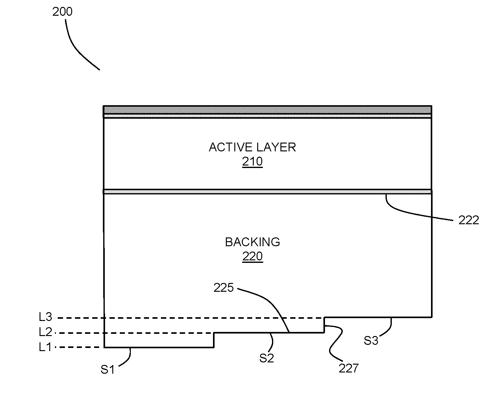
[0120]In the present example design, a transducer with a segmented backing was fabricated, and the acoustic response was experimentally measured and mathematically modeled. FIG. 9 is an illustration of the segmented backing of the transducer design. As shown in the Figure, the example transducer is a single-element transducer with a polygonal aperture, having a backing layer 800 that is segmented into seven levels (L1-L7), where the areas of the various segments are equal. The active and matching layers are not shown in the Figure. The section 820 to the right of the dark band is not active. The distal surface of the backing layer includes the segmented surface define by the segments forming the seven levels L1-L7, and two additional base regions 805 and 810 of the backing at the upper and lower ends thereof. The thickness of the backing is t...


PUM


Abstract

Methods and devices are provided for suppressing reverberations within an ultrasound transducer with a backing whereby the backing may not sufficiently attenuate the acoustic energy by means of acoustic absorption and scattering alone. At least a portion of a surface of the backing is segmented into a plurality of levels defined by surface segments. The levels may be are spatially offset so that acoustic reflections from the segmented surface are spread out in time, thereby decreasing the net amplitude of the internally reflected waves as they interact with the piezoelectric layer. Adjacent (neighbouring) levels may be spatially offset by a longitudinal distance equaling approximately an odd number multiple of a quarter of an operational wavelength of the transducer, so that destructive interference occurs from acoustic waves reflected from adjacent levels. Various example configurations of segmented surfaces are described, and methods for selecting a profile of a segmented surface are provided.

Description

CROSS-REFERENCE TO RELATED APPLICATION[0001]This application claims priority to U.S. Provisional Application No. 61 / 907,765, titled “ULTRASONIC TRANSDUCER WITH BACKING HAVING SPATIALLY SEGMENTED SURFACE” and filed on Nov. 22, 2013, the entire contents of which is incorporated herein by reference.BACKGROUND[0002]The present disclosure relates to ultrasonic transducers. More particularly, the present disclosure relates to ultrasonic imaging and therapeutic devices.[0003]Ultrasonic transducers are employed in a wide array of applications and industries, and are commonly employed in therapeutic and imaging devices.[0004]Typically, an ultrasound transducer includes an active piezoelectric element that is attached to a backing, where the backing is made from a material that prevents spurious acoustic reflections from reaching the active element and interfering with its performance. The backing of an ultrasonic transducer is usually designed to be sufficiently thick to reduce spurious acou...

Claims


Application Information

Patent Timeline
IPC IPC(8): B06B1/06A61B8/12A61B8/00
CPCB06B1/0685A61B8/12A61B8/4483B06B1/0622G01D5/48G01S15/8909G10K11/002G01N29/36
Inventor LUKACS, MARCCOURTNEY, BRIANMUNDING, CHELSEA
Owner SUNNYBROOK HEALTH SCI CENT
Why Eureka
Try Eureka