Burring method and burring apparatus

Active Publication Date: 2016-11-24
NIPPON STEEL CORP
View PDF14 Cites 0 Cited by
  • Summary
  • Abstract
  • Description
  • Claims
  • Application Information

AI Technical Summary

Benefits of technology

[0086]According to the aspects, it is possible to accurately and effectively form burring holes having the same

Problems solved by technology

As a result, there is a problem that the weight of the link structure member increases.
As a result, it is necessary to stably hold a bush or the like within ranges of the thicknesses of the facing wall portions configuring the joining portions, and stably holding the bush or the like is

Method used


Image

  • Burring method and burring apparatus
  • Burring method and burring apparatus
  • Burring method and burring apparatus

Examples


Example

First Embodiment

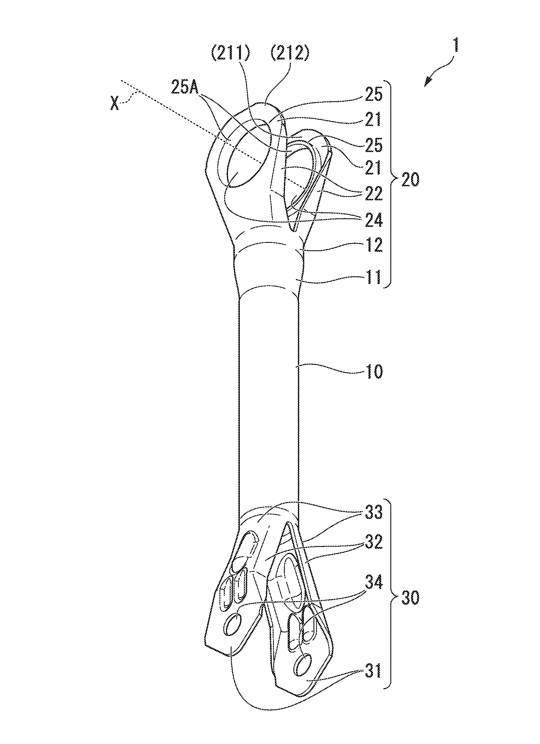
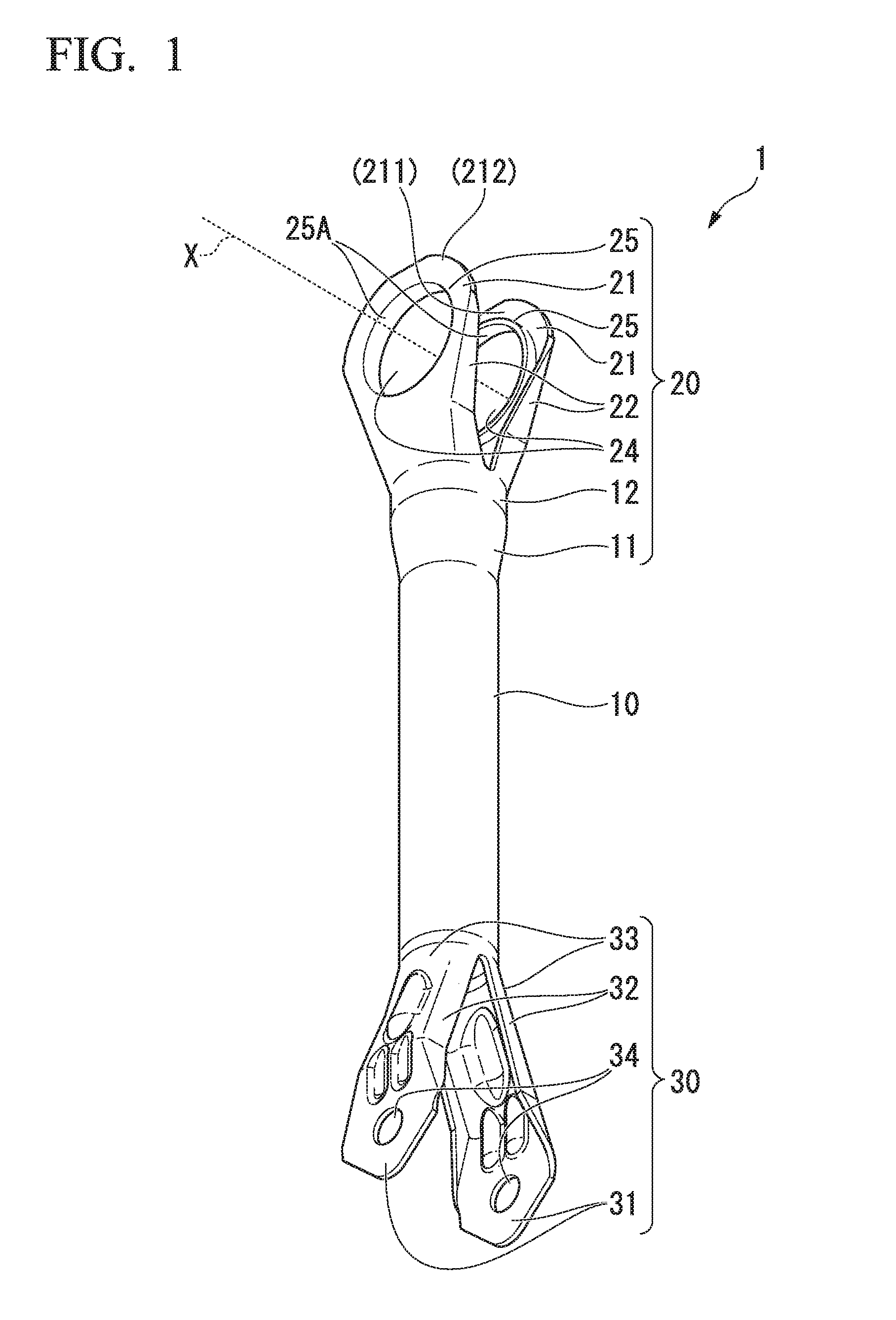
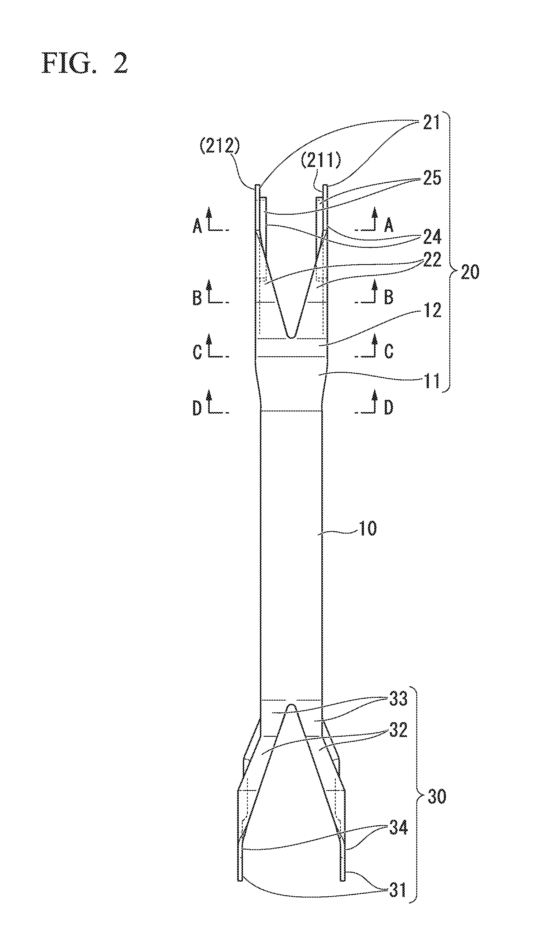
[0181]First, a burring apparatus and a burring method according to a first embodiment of the present invention will be described. In the first embodiment, as shown in FIGS. 1 and 2, a burring apparatus and a burring method for forming the burring hole having the rising wall portion which is bent toward the inside of the first wall portion 211 on the first wall portion 211, and the burring hole having the rising wall portion which is bent toward the inside of the second wall portion 212 on the second wall portion 212 will be described.

[0182]Moreover, in both sides of the first wall portion 211 on the first axis line X, the side on which the second wall portion 212 exists is defined as an “inside of the first wall portion 211”, and the opposite side is defined as an “outside of the first wall portion 211”. In addition, in both sides of the second wall portion 212 on the first axis line X, the side on which the first wall portion 211 exists is defined as an “inner side ...

Example

Second Embodiment

[0292]Next, a burring apparatus and a burring method according to a second embodiment of the present invention will be described. In the second embodiment, a burring apparatus and a burring method for forming a burring hole having a rising wall portion which is bent toward the outside of the first wall portion 211 on the first wall portion 211, and a burring hole having a rising wall portion which is bent toward the outside of the second wall portion 212 on the second wall portion 212 will be described.

[0293]FIG. 13A is a side sectional view of a burring apparatus 400 according to the second embodiment. FIG. 13B is a front sectional view of the burring apparatus 400 according to the second embodiment. In addition, FIG. 13A is a view when the burring apparatus 400 is viewed along the cross section including the first axis line X and the second axis line Y. FIG. 13B is a view when the burring apparatus 400 is viewed along the cross section including the first axis lin...

Example

Third Embodiment

[0378]Next, a burring apparatus and a burring method according to a third embodiment of the present invention will be described. In the third embodiment, a burring apparatus and a burring method for forming a burring hole having a rising wall portion which is bent toward the outside of the first wall portion 211 on the first wall portion 211, and a burring hole having a rising wall portion which is bent toward the outside of the second wall portion 212 on the second wall portion 212 will be described. That is, the third embodiment is a modification example of the second embodiment.

[0379]FIG. 19A is a side sectional view of a burring apparatus 500 according to the third embodiment. FIG. 19B is a front sectional view of the burring apparatus 500 according to the third embodiment. In addition, FIG. 19A is a view when the burring apparatus 500 is viewed along the cross section including the first axis line X and the second axis line Y. FIG. 19B is a view when the burring...


PUM

PropertyMeasurementUnit
Forceaaaaaaaaaa
Pressureaaaaaaaaaa

Abstract

In the present invention, in a piercing punch and a burring punch which are shaft members having a first axis line as the center axis lines and are provided so as to be movable along the first axis line, first, after prepared holes having the first axis line as the center axis lines with respect to the first wall portion and the second wall portion are formed using the piercing punch, burring holes having the first axis line as the center axis lines with respect to the first wall portion and the second wall portion are formed using the burring punch.

Description

TECHNICAL FIELD OF THE INVENTION[0001]The present invention relates to a burring method and a burring apparatus.[0002]Priority is claimed on Japanese Patent Application No. 2014-014817, filed on Jan. 29, 2014, the content of which is incorporated herein by reference.RELATED ART[0003]As is well known, as a link structure member which connects a plurality of objects to each other, a link structure member in which a joining portion is formed on an end portion or an intermediate position of a link structure member has been put into practical use. For example, the link structure member is used in various applications such as a link structure member for a construction structure, a link structure member for a suspension of an automobile, or the like.[0004]For example, as the suspension device of an automobile, various types of suspension devices have been put into practical use, and for example, in a five-link type suspension, suspension links such as a lower link, an upper link, or a late...

Claims


Application Information

Patent Timeline
IPC IPC(8): B21D28/16
CPCB21D28/16B21D41/025B21D28/14B21D28/28
Inventor SHIRAKAMI, SATOSHIMIZUMURA, MASAAKIYOSHIDA, TOHRU
Owner NIPPON STEEL CORP
Why Eureka
Try Eureka