Light-emitting signboard

a signboard and light-emitting technology, applied in the field of signboard technology, can solve the problems of increasing the power consumption of leds and uneven light brightness, and achieve the effect of producing more uniform light and minimizing power consumption

Inactive Publication Date: 2017-02-23
LEDYOUNG TECH CORP
View PDF10 Cites 1 Cited by
  • Summary
  • Abstract
  • Description
  • Claims
  • Application Information

AI Technical Summary

Benefits of technology

[0006]The present invention has been accomplished under the circumstances in view. It is therefore the main object of the present invention to provide a light-emitting signboard, which effectively produces more uniform light with minimized power consumption.
[0007]To achieve this and other objects of the present invention, a light-emitting signboard comprises a light guide plate having a light-emitting region on a front surface thereof and a plurality of light diffusing portions located in the light-emitting region and configured to refract and diffuse light, and at least one light source configured to emit light into the light guide plate through one peripheral edge thereof, wherein the total surface area of the light diffusing portions is larger than or equal to one half of the surface area of the light-emitting region, and, the density of the light-emitting regions in the light diffusing portion at the area adjacent to the light source is smaller than the density of the light-emitting regions at the area far from the light source. Thus, the light-emitting region can produce more uniform light.

Problems solved by technology

However, when a large number of light diffusing components is arranged in the light guide plate, the area adjacent to the LED-based light source will be more bright than the area far from the LED-based light source, resulting in uneven brightness of light.
However, this method relatively increases the power consumption of the LEDs.

Method used


Image

  • Light-emitting signboard
  • Light-emitting signboard
  • Light-emitting signboard

Examples


Embodiment Construction

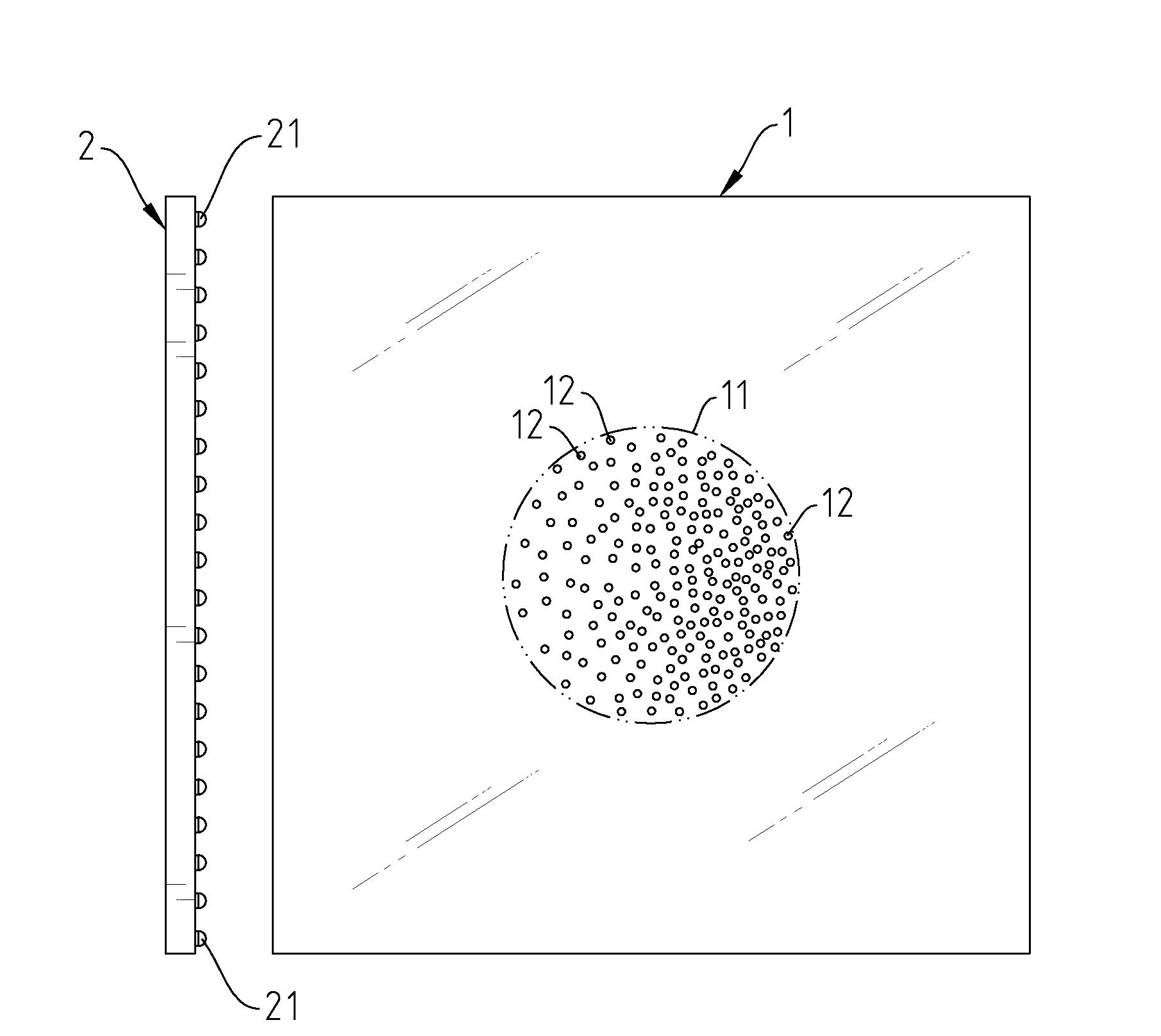
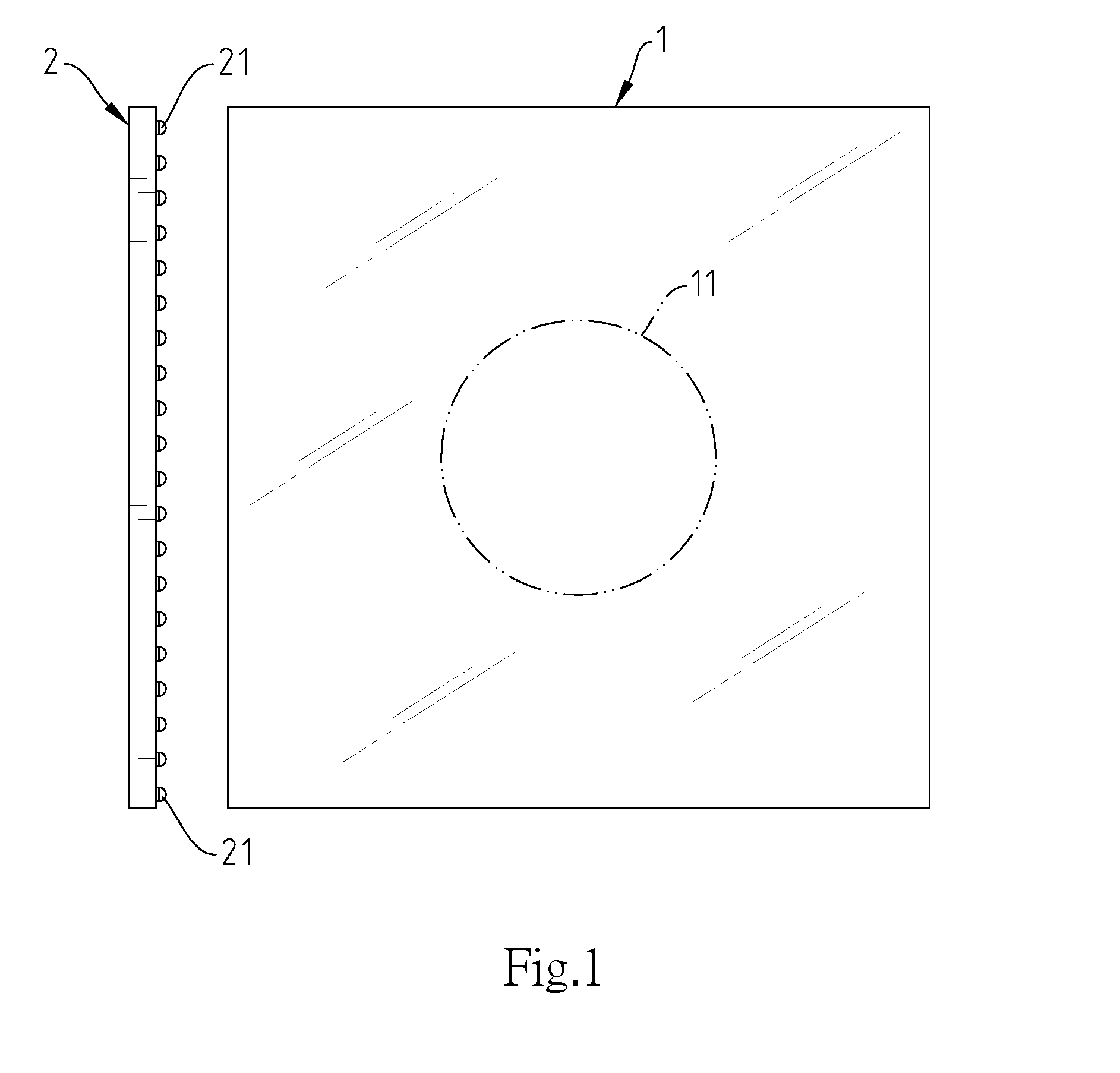
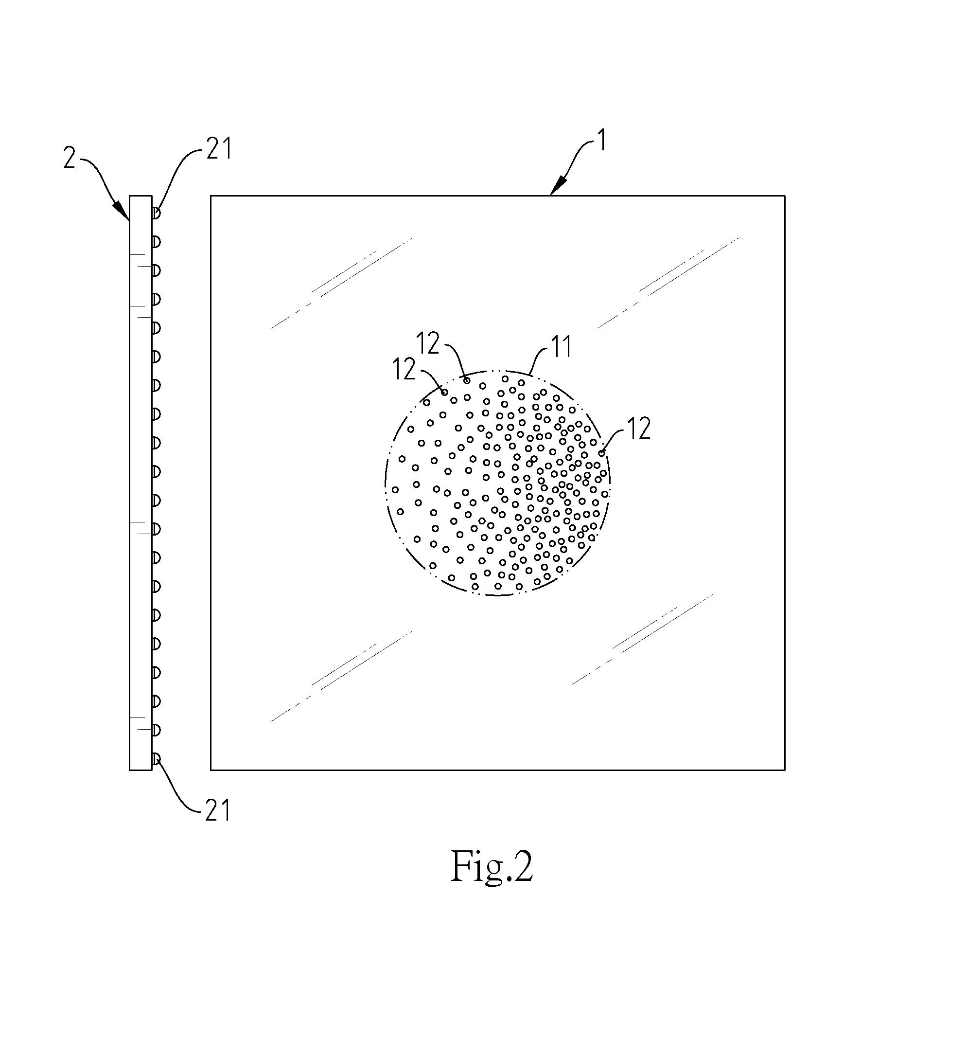
[0015]Referring to FIGS. 1-3, a light-emitting signboard in accordance with the present invention is shown. The light-emitting signboard comprises a light guide plate 1, and a light source 2 disposed at one lateral side of the light guide plate 1.

[0016]The light guide plate 1 comprises a light-emitting region 11 on a front surface thereof, and a plurality of light diffusing portions 12 disposed in the light-emitting region 11 and configured to refract and diffuse light. The light diffusing portions 12 have the same size and shape. In this embodiment, the light diffusing portions 12 are inwardly curved concave surface portions of the light-emitting region 11 of the light guide plate 1. Further, the total surface area of these light diffusing portions 12 is larger than or equal to one half of the surface area of the light-emitting region 11. In one example of the present invention, the surface area of the light-emitting region 11 is 100 cm2; the surface area of each light diffusing po...


PUM


Abstract

A light-emitting signboard includes a light guide plate having a light-emitting region on a front surface thereof and a plurality of light diffusing portions located in the light-emitting region and configured to refract and diffuse light, and a light source configured to emit light into the light guide plate through one peripheral edge thereof. The total surface area of the light diffusing portions is larger than or equal to one half of the surface area of the light-emitting region, and, the density of the light-emitting regions in the light diffusing portion at the area adjacent to the light source is smaller than the density of the light-emitting regions at the area far from the light source.

Description

BACKGROUND OF THE INVENTION[0001]1. Field of the Invention[0002]The present invention relates to signboard technology and more particularly, to a light-emitting signboard, which has light diffusing portions arranged in a light-emitting region of a light guide plate thereof for producing more uniform light with less power consumption.[0003]2. Description of the Related Art[0004]Light-emitting signboards are widely used for advertisement, road sign and escape indication applications. Regular light-emitting signboards commonly comprise a light guide plate, a LED-based light source configured to emit light into the light guide plate, and light diffusing components mounted in the light guide plate and configured to refract and diffuse light toward the outside of the light guide plate.[0005]Generally, increasing the number of the light diffusing components in the light guide plate enhances light diffusing and lowers LED power consumption. However, when a large number of light diffusing co...

Claims


Application Information

Patent Timeline
Patent Type & Authority Applications(United States)
IPC IPC(8): F21V8/00
CPCG02B6/0061G02B6/0073G02B6/0068G02B6/0051G02B6/0036G02B6/006
Inventor HSU, YEN-CHOU
Owner LEDYOUNG TECH CORP
Why Eureka
Try Eureka