Check patentability & draft patents in minutes with Patsnap Eureka AI!

Cooling system for power transmission unit

a technology for power transmission units and cooling systems, applied in the direction of gearing details, vehicle sub-unit features, gearing, etc., can solve the problem of insufficient cooling of transmission, and achieve the effect of reducing the amount of oil, reducing the cost of cooling systems, and efficient collection

Active Publication Date: 2017-04-06
TOYOTA JIDOSHA KK
View PDF27 Cites 5 Cited by
  • Summary
  • Abstract
  • Description
  • Claims
  • Application Information

AI Technical Summary

Benefits of technology

The present application aims to provide a cooling system for a power transmission unit that can effectively cool a cooling site while reducing manufacturing costs. The system uses oil cooled by an oil cooler and two oil pipes are arranged in the housing chamber to deliver the oil to the motor for cooling. The oil splashed in the chamber can be efficiently applied to the cooling site by guiding it to the catch tank using the oil pipes. The system also allows for the circulation of oil within the housing chamber, which can downsize the catch tank and reduce the amount of oil needed, further reducing manufacturing costs.

Problems solved by technology

For this reason, the transmission may not be cooled sufficiently by such splash lubrication of the oil.

Method used


Image

  • Cooling system for power transmission unit
  • Cooling system for power transmission unit
  • Cooling system for power transmission unit

Examples


Embodiment Construction

)

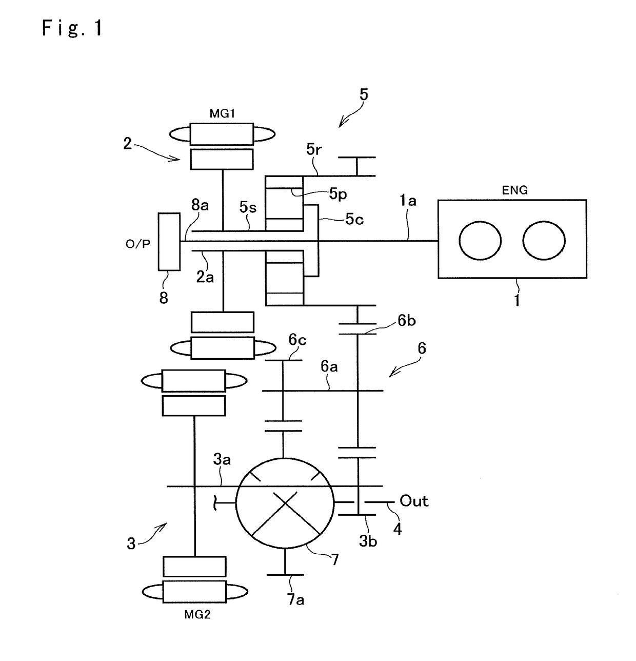
[0026]Preferred embodiment of the present application will now be explained with reference to the accompanying drawings. Referring now to FIG. 1, there is shown one example of a powertrain of a hybrid vehicle Ve to which the cooling system according to the embodiment is applied. Specifically, the vehicle Ve is a so-called a “two-motor type” hybrid vehicle in which a prime mover includes an engine (referred to as “ENG” in FIG. 1) 1 such as a gasoline engine and a diesel engine, a first motor (referred to as “MG1” in FIGS. 1 and 2) 2, and a second motor (referred to as “MG2” in FIGS. 1 and 2) 3. An output power of the engine 1 is distributed to the first motor 2 and to a driveshaft 4, and an output power of the second motor 3 is delivered directly to the driveshaft 4.

[0027]Each of the first motor 3 and the second motor 4 is a motor-generator that is operated as a motor by applying an electric power thereto generate a torque, and that is operated as a generator by applying a torque th...


PUM


Abstract

A cooling system for a power transmission unit that can cool a cooling site effectively is provided. The cooling system comprises: an oil pump; an oil cooler that cools the oil delivered from the oil pump; a first oil pipe for delivering the oil from the oil pump to the oil cooler; a second oil pipe for delivering the oil cooled by the oil cooler to a heat generating element. A housing chamber includes a high-temperature section where the heat generating element is arranged, and a low-temperature section. The second oil pipe is arranged in the housing chamber while passing through the low-temperature section, and an opening is formed on the second oil pipe in such a manner as to open toward the heat generating element.

Description

CROSS REFERENCE TO RELATED APPLICATIONS[0001]The present invention claims the benefit of priority to Japanese Patent Application No. 2015-196682 filed on Oct. 2, 2015 with the Japanese Patent Office, the entire contents of which are incorporated herein by reference in its entirety.BACKGROUND[0002]Field of the Invention[0003]Embodiments of the present application relates to the art of a power transmission unit such as a transmission, a transaxle and a differential unit, and especially to a hydraulic cooling system for a power transmission unit.[0004]Discussion of the Related Art[0005]JP-A-2015-034581 describes an oil supply device of a hybrid vehicle having a first motor and a second motor. According to the teachings of JP-A-2015-034581, oil in a transmission is delivered to an oil sump passage by a rotation of a final gear to lubricate an oil requiring site. In the transmission, the oil is also delivered to an oil introduction passage by rotations of an output gear and a counter gea...

Claims


Application Information

Patent Timeline
IPC IPC(8): F16H57/04B60K6/405B60K6/365
CPCF16H57/0412F16H57/0476F16H57/0423F16H57/0484B60K6/365B60K6/405B60Y2400/73Y10S903/91Y10S903/952B60Y2200/92B60Y2306/03B60Y2306/05F16H37/0806F16H57/0413F16H57/0436F16H3/727F16H57/0417F16H57/0453F16H57/0457B60K6/445Y02T10/62
Inventor ONO, TOMOHITOHASHIMOTO, HIROTOKIMURA, HIROAKI
Owner TOYOTA JIDOSHA KK
Features
  • R&D
  • Intellectual Property
  • Life Sciences
  • Materials
  • Tech Scout
  • Unparalleled Data Quality
  • Higher Quality Content
  • 60% Fewer Hallucinations
Learn More