Wavelength converter, illuminator, and projector

Active Publication Date: 2017-04-06
SEIKO EPSON CORP
View PDF13 Cites 5 Cited by
  • Summary
  • Abstract
  • Description
  • Claims
  • Application Information

AI Technical Summary

Benefits of technology

[0026]The projector according to the third aspect, which includes the illuminator according to the second aspect described

Problems solved by technology

In the technology of related art described above, since the heat is transferred to the cooling fins provided on the rear surface of the substrate

Method used


Image

  • Wavelength converter, illuminator, and projector
  • Wavelength converter, illuminator, and projector
  • Wavelength converter, illuminator, and projector

Examples


Embodiment Construction

[0035]An embodiment of the invention will be described below in detail with reference to the drawings.

[0036]In the drawings used in the following description, a characteristic portion is enlarged for convenience in some cases for clarity of the characteristic thereof, and the dimension ratio and other factors of each component are therefore not always equal to actual values.

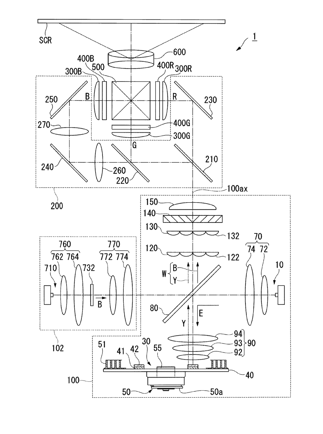
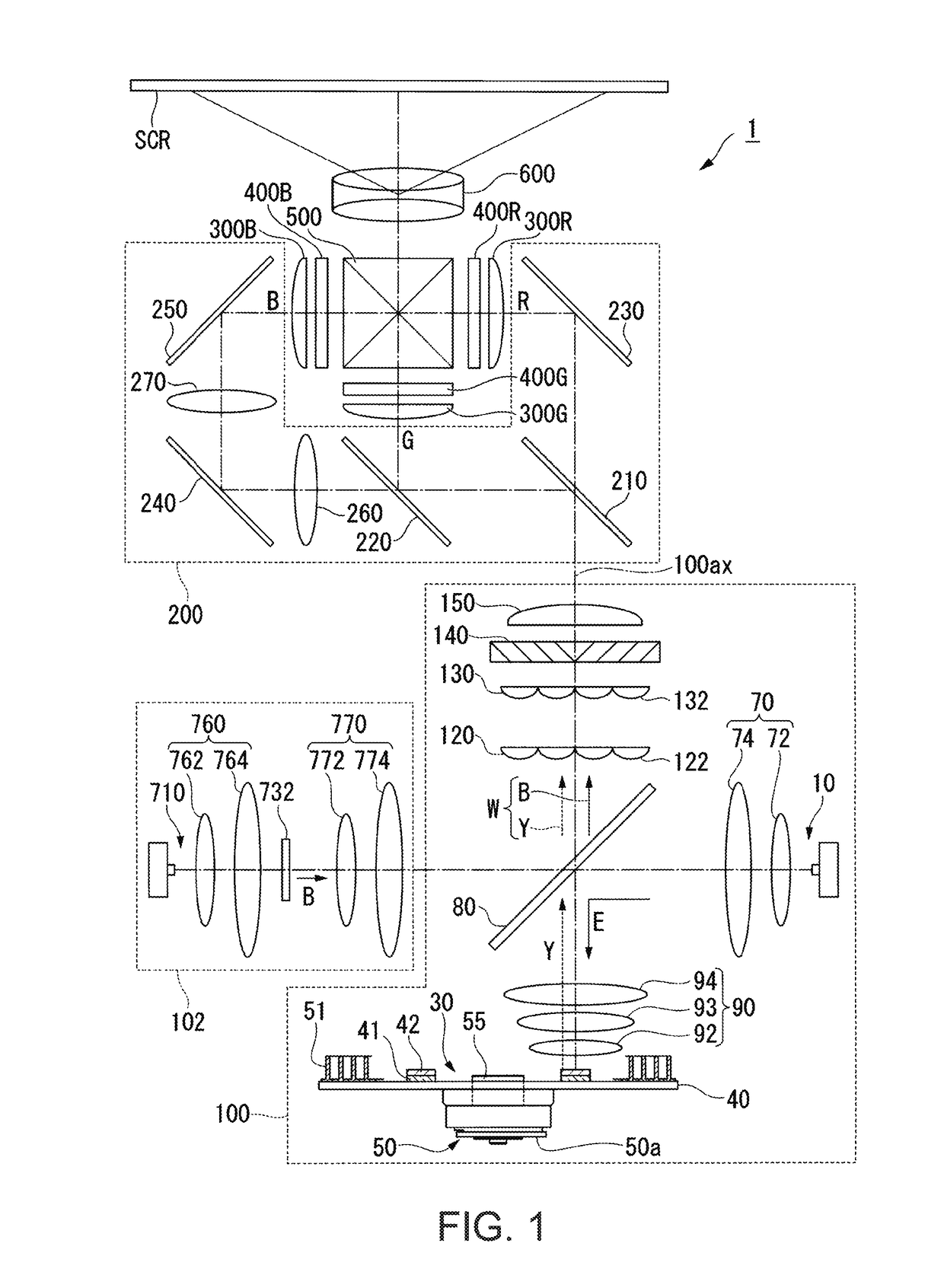
[0037]An example of a projector according to the present embodiment will be described. A projector 1 according to the present embodiment is a projection-type image display apparatus that displays color video images on a screen SCR (projection surface).

[0038]FIG. 1 is a top view showing the optical system of the projector 1 according to the present embodiment.

[0039]The projector 1 includes a first illuminator 100 (illuminator), a second illuminator 102, a color separation / light guide system 200, liquid crystal light modulators 400R, 400G, and 400B (light modulators) corresponding to red light, green light, and blu...


PUM


Abstract

A wavelength converter includes a rotating device, a substrate rotated by the rotating device, and a wavelength conversion element and a plurality of fins provided on a first surface of the substrate, and the first surface is so provided as to face an opening of an air introduction channel through which air for cooling the wavelength conversion element is introduced.

Description

CROSS-REFERENCE TO RELATED APPLICATION[0001]The entire disclosure of Japanese Patent Application No. 2015-198266, filed Oct. 6, 2015 is expressly incorporated by reference herein.BACKGROUND[0002]1. Technical Field[0003]The present invention relates to a wavelength converter, an illuminator, and a projector.[0004]2. Related Art[0005]In recent years, a phosphor is used as an illuminator for a projector.[0006]In the illuminator described in JP-A-2012-013897, the rear surface of a substrate that supports a phosphor is provided with cooling fins. The substrate and the cooling fins are integrated with each other.[0007]The phosphor supporting surface of the substrate receives excitation light directed to the phosphor, and the temperature of the surface therefore tends to increase. In the technology of related art described above, since the heat is transferred to the cooling fins provided on the rear surface of the substrate that supports the phosphor and the phosphor is therefore indirectl...

Claims


Application Information

Patent Timeline
IPC IPC(8): G03B21/16G02B26/00F21V29/83F21V9/16F21V29/502F21V29/78G03B21/20G02B7/00
CPCG03B21/16G03B21/204G02B26/008G02B7/008F21Y2115/30F21V29/502F21V29/78F21V29/83F21V9/16
Inventor TAKAGI, KUNIHIKO
Owner SEIKO EPSON CORP
Why Eureka
Try Eureka