
Machining center

a technology of machining center and display screen, which is applied in the direction of manufacturing tools, lighting elements, lighting and heating equipment, etc., can solve the problems of difficult visual inspection of the presence or absence of displayed information, failure to confirm, and misunderstanding of displayed information, so as to achieve high quality and high durability. , the effect of hardening the surfa

Active Publication Date: 2015-05-19
KITAMURA MACHINERY
View PDF1 Cites 3 Cited by
  • Summary
  • Abstract
  • Description
  • Claims
  • Application Information

AI Technical Summary

Benefits of technology

The present invention is about a machining center that allows for easy visual checking of a machine tool from far away. The invention includes an LED display means on the front of the machine tool body or the arched door portion. The operation door is made of carbon fiber, which has the advantages of being strong, durable, and having a high-quality look. Additionally, the carbon fiber material is malleable, allowing for little strength to open and close the door. The invention enables quick visual inspection of the machine tool operation state from a distance.

Problems solved by technology

However, it has been difficult to visually check the presence or absence of displayed information on the LED display means at a position where the processing portion front of the tool body is hardly visible, for example, at a side distant from the tool body.
The operator may fail to confirm displayed information on the LED display means or may misunderstand the displayed information.
A steel door has disadvantages: (a) heavy; (b) painting needed; and (c) easily scarred.
A door made of ordinary resin (FRP) has disadvantages: (d) low in intensity and easily destructible and (e) easily scarred soft surface.

Method used


Image

  • Machining center
  • Machining center
  • Machining center

Examples


Embodiment Construction

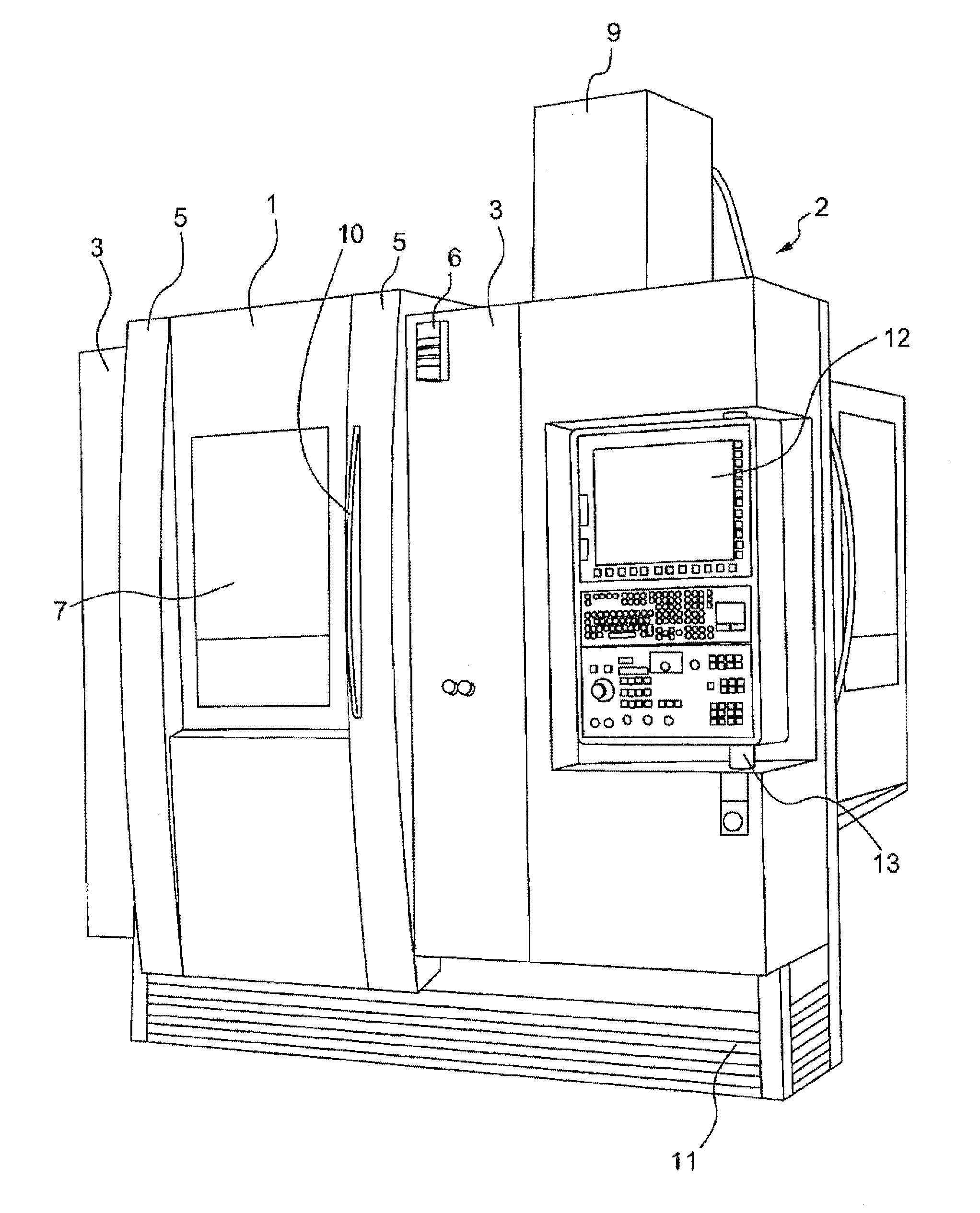
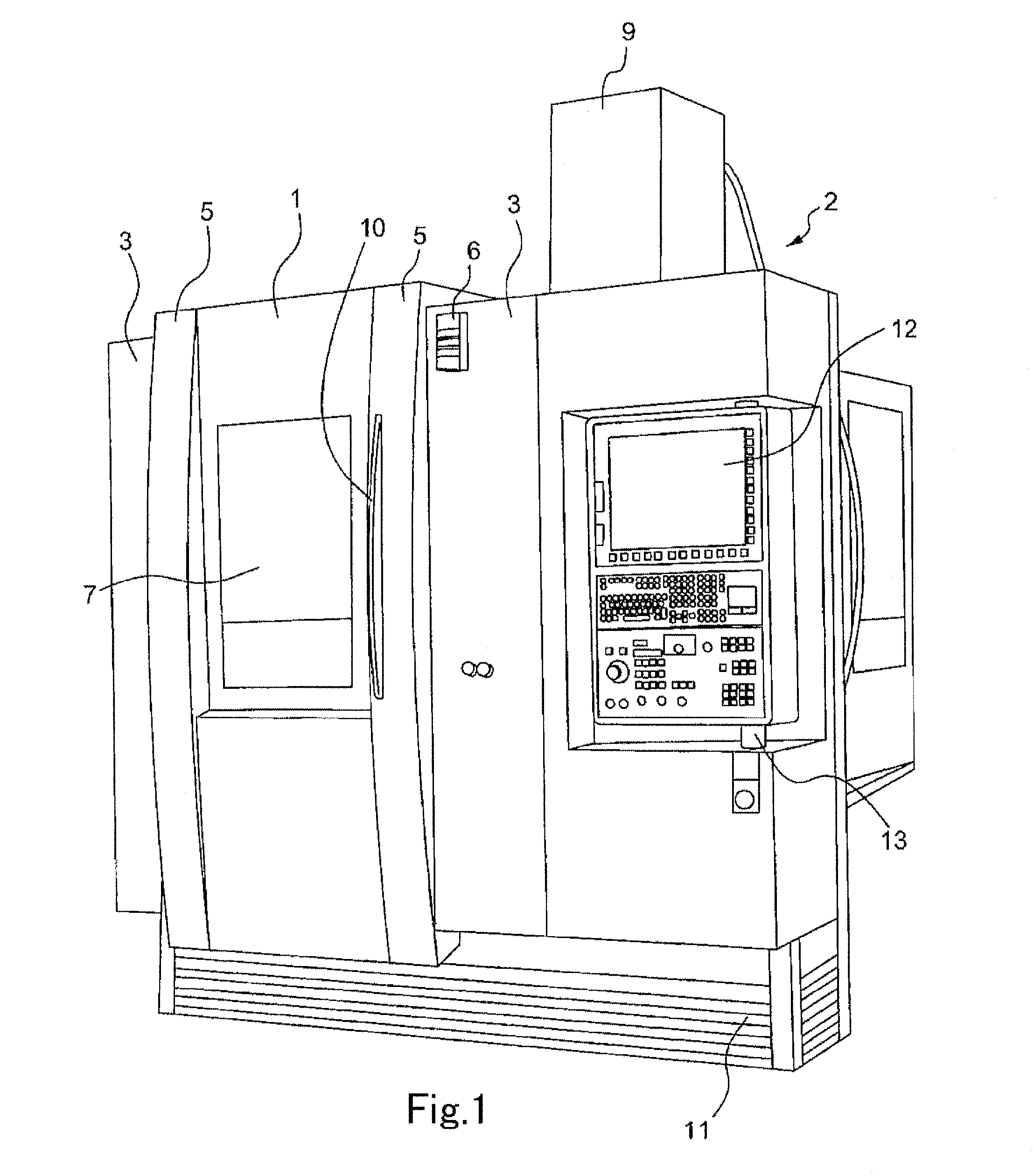
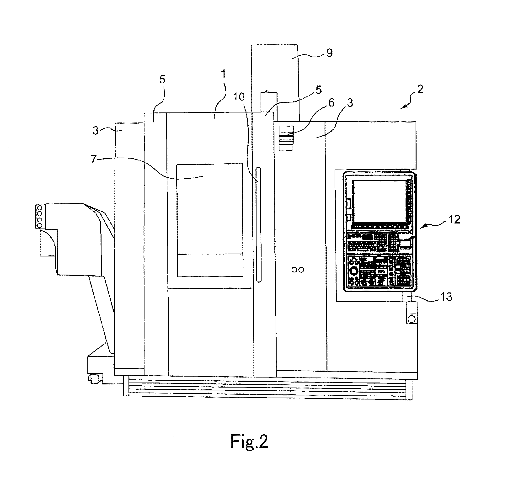
[0040]FIGS. 1 through 6 illustrate the machining center according to an embodiment of the invention.

[0041]As shown in FIGS. 1 through 6, an openable and closable operation door 1 is provided for the front of a processing portion of the machine tool. The operation door 1 is arched along a vertical direction from the surface of a guard 3 of a tool body 2. The operation door 1 extends between the top and bottom ends of the guard 3 of the tool body 2. The operation door 1 is curved on an arched line that reaches a highest point at its center and lowers toward the top and bottom ends.

[0042]LED display means 6 may be provided for only one of two sides 5 of the operation door 1. Alternatively, the LED display means 6 may be provided for both sides 5 of the operation door 1.

[0043]The LED display means 6 may be provided adjacently to or away from the side 5 of the operation door 1.

[0044]The LED display means 6 is favorably formed to be half-round to protrude from the surface of the guard 3. ...


PUM


Abstract

A machining center is provided with a guard that covers a processing portion of a machine tool. An openable and closable operation door is provided at the guard front. The operation door is arched along a vertical direction from the guard surface. The operation door is provided with a handle used to open and close the operation door. The operation door is curved on an arched line that reaches a highest point at its center and lowers toward the top and bottom ends. The guard is provided with half-round LED display means protruding from the guard surface. The operation door is made of carbon fiber.

Description

BACKGROUND OF THE INVENTION[0001]1. Field of the Invention[0002]The present invention relates to a machining center that is provided with a guard for covering a processing portion of a machine tool and is provided with an openable and closable operation door in front of the guard.[0003]2. Description of Related Art[0004]This type of operation door is conventionally known.[0005]As a known technology, a flat fixed portion at a processing portion front of a machine tool body is vertically provided with elongate and flat LED display means away from an operation door provided for a guard. In this case, an operator can visually check the presence or absence of displayed information on even the flat LED display means away from the tool at a position where the operator can easily view the processing portion front of the tool body. However, it has been difficult to visually check the presence or absence of displayed information on the LED display means at a position where the processing port...

Claims


Application Information

Patent Timeline
Patent Type & Authority Patents(United States)
IPC IPC(8): F21V33/00B23Q17/24B23Q11/08
CPCB23Q17/24B23Q11/0891B23Q11/08B23Q17/00B23Q1/0045
Inventor KITAMURA, AKIHIRO
Owner KITAMURA MACHINERY
Learn More