Manufacturing method and continuous drying apparatus for head decorating regenerated collagen fiber

a technology drying apparatus, which is applied in the direction of drying machines with progressive movements, lighting and heating apparatus, furniture, etc., can solve the problems of affecting the commercial value, affecting the effect of the situation of not being practicable for continuous drying of regenerated collagen fiber, so as to prevent the occurrence of fluff, prevent process trouble, and reduce tension differences

Active Publication Date: 2008-03-04
KANEKA CORP
View PDF9 Cites 3 Cited by
  • Summary
  • Abstract
  • Description
  • Claims
  • Application Information

AI Technical Summary

Benefits of technology

[0015]An object of the present invention is an industrially applicable continuous drying method and apparatus enabling manufacture of head decorating regenerated collagen fibers with outstanding quality, the method and apparatus causing no process trouble despite variation of shrinking behavior of the regenerated collagen fibers induced by drying under various conditions having different temperature, humidity, etc.
[0016]As a result of wholehearted investigations performed by the present inventors, it was found out that twists given with a predetermined rate to a fiber bundle introduced into a drying chamber, and furthermore drying under control within a certain range of a tension of the fiber bundle under drying enabled continuous drying of a regenerated collagen fiber, leading to completion of the present invention.

Problems solved by technology

Furthermore, there are problems that an excessively reduced tension under drying for fear of yarn breakage increases shrinkage of the regenerated collagen fiber under drying, and further fails to retain the curl retentive property as one of important quality of head decorating fibers at termination of drying, impairing commercial value thereof.
From the viewpoint of improving productivity, development of a continuous drying method and a device therefor is necessary, but there are problems of occurrence of fluff (yarn breakage) and tension control of a fiber running in a dryer etc., and therefore continuous drying of a regenerated collagen fiber is not yet in a situation of practical use.
In contrast, regenerated collagen fibers can not allow stretching under drying, and compulsory stretching forms break of fiber bundles and causes resultant process trouble.
Furthermore continuous drying without stretching makes the fiber bundles under drying give drying unevenness, forms difference in the shrinkage length in the fiber bundle, and forms resulting fiber bundle hang-down in a following drying step, thus leading to wound around rollers of the hung down bundle, and to slipping of the fiber out of the rollers.
As a result, these disadvantages cause fiber breakage or breaking of the fiber bundle, and lead to situation of operation failure.
However, adoption of this apparatus in drying of regenerated collagen fibers makes difficult maintenance of a fixed fiber tension between each of the driven rollers.
The difficulties are attributed to the fact that drying shrinkage takes place immediately after the fibers come into falling rate drying region in drying of regenerated collagen fibers, and a change of drying conditions greatly varies shrinking behavior of the fibers, and makes difficult determination of a specified position of shrinkage of the fiber within the dryer, therefore shifting the shrinking position within the dryer.
Accordingly, control of shrinking behavior of the fibers is very difficult to be adjust to a reduction ratio of the driven rollers, that is sections having a higher fiber tension and a lower one may be formed, a section having a higher fiber tension gives fiber breakage (fluff), and a section having a lower section gives fiber hang-down, leading to process trouble.
In the case where this apparatus is adopted for drying of regenerated collagen fibers, however, the above-described disadvantages make difficult adjustment of a tapered angle of the Nelson rollers or the tapered rollers with respect to shrinking behavior of the fibers, and therefore a section having a higher fiber tension gives fiber breakage (fluff), and a section having a lower section gives fiber hang-down.
However, when these heat rollers used in drying regenerated collagen fibers, a usual straight drum type heat roller makes the fiber continuously shrink and raise a tension thereof as drying advances.
As a result, control of tension becomes uncontrollable, leading to inevitable breaking of the fiber bundle (tow).
Therefore, in the case of regenerated collagen fibers, use of the heat roller alone in continuous drying operation may not be adopted.
Accordingly, realization of a dryer having one pass of not less than 90 m either by horizontal or vertical type is very difficult, in consideration of conditions for installation construction cost, operability, etc., and therefore adoption a single passage dryer having no rollers within the dryer in drying for regenerated collagen fibers may not be practical.
As previously described, in manufacturing of head decorating regenerated collagen fibers, there have not yet been found out methods and apparatus enabling continuous drying, without any process trouble, of the regenerated collagen fibers having outstanding quality.

Method used


Image

  • Manufacturing method and continuous drying apparatus for head decorating regenerated collagen fiber
  • Manufacturing method and continuous drying apparatus for head decorating regenerated collagen fiber
  • Manufacturing method and continuous drying apparatus for head decorating regenerated collagen fiber

Examples


example 2

[0067]Experiment was conducted in a same manner as in Example 1 except for having changed a count of twists of 0.5 twists / m into 1.0 twists / m. As a result, fiber shrinkage gave 7% and a number of fluff (fiber breakage) and hackling loss rate exceeded acceptance criteria, and curl retentive property was also satisfactory.

example 3

[0068]Experiment was conducted in a same manner as in Example 1 except for having changed a count of twists of 0.5 twists / m into 0.25 twists / m. As a result, fiber shrinkage gave 7%. Convergence of the fiber bundle was inferior as compared with Example 1, a number of fluff (fiber breakage) gave 30 times and a hackling loss rate increased to 0.3%, a number of fluff and a hackling loss rate exceeded acceptance criteria, and curl retentive property was also satisfactory.

example 4

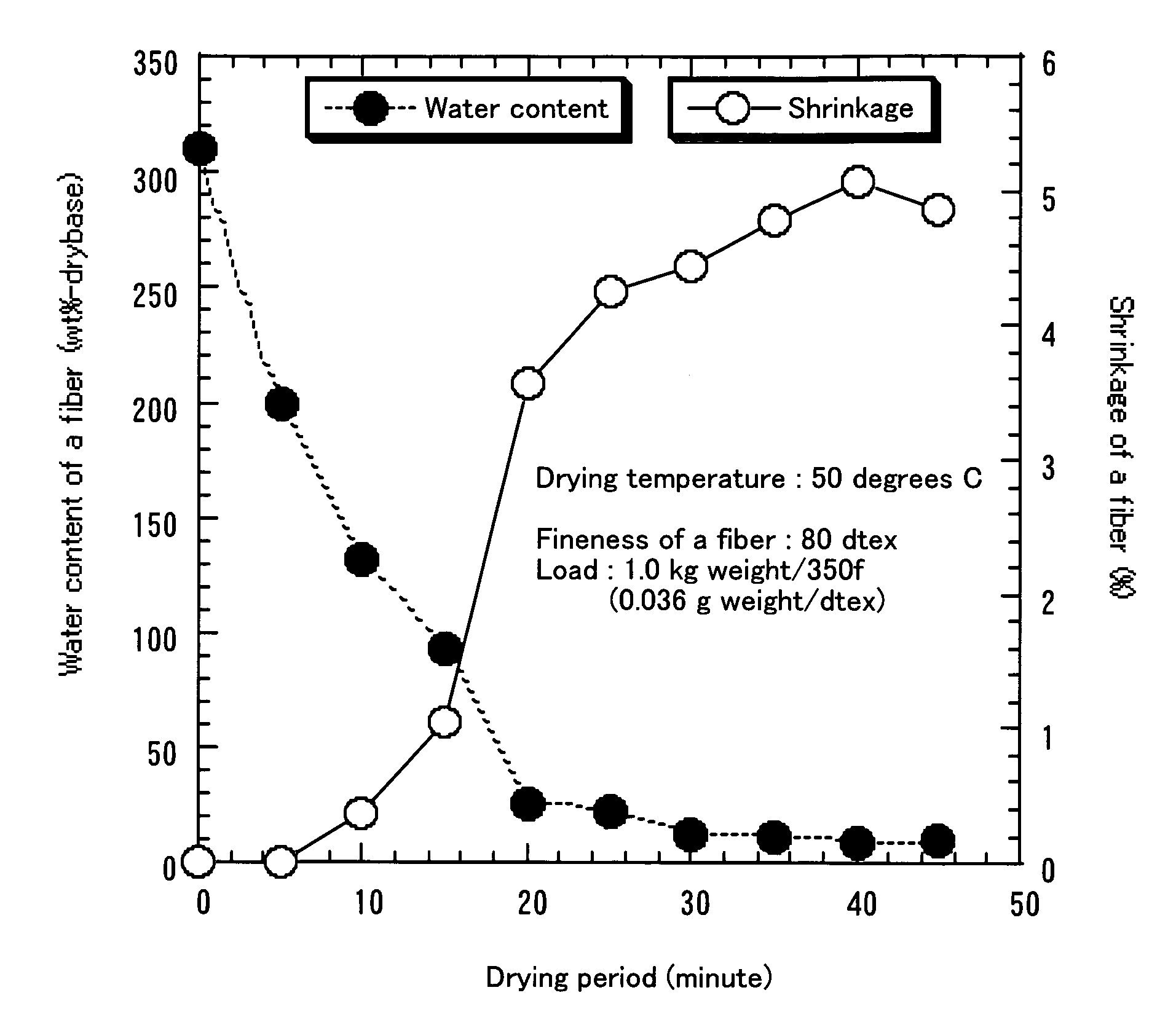
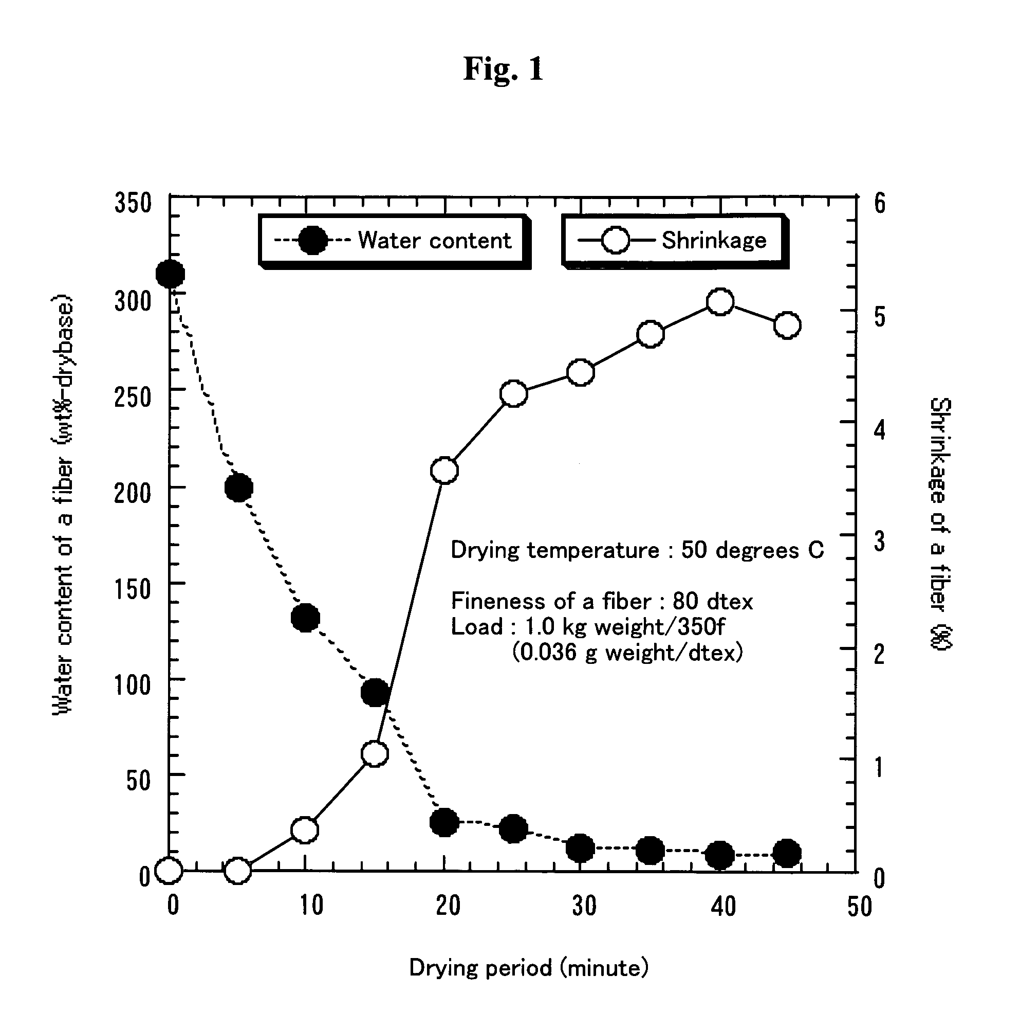
[0069]Experiment was conducted in a same manner as in Example 1 except for having changed a drying temperature of 65 degree C. into 50 degree C. As a result, fiber shrinkage gave 5%. A number of fluff (fiber breakage) and a hackling loss rate exceeded acceptance criteria, and curl retentive property was also satisfactory.


PUM

PropertyMeasurementUnit
residence lengthaaaaaaaaaa
diameteraaaaaaaaaa
diameteraaaaaaaaaa

Abstract

Provided is a method for manufacturing a regenerated collagen fiber and a drying apparatus therefor in a manufacturing process of a head decorating regenerated collagen fiber, the method enabling suppression of fluff (fiber breakage) and process trouble and providing outstanding curl retentive property and little hackling loss. Continuous drying is performed while controlling a tension of a fiber bundle under drying, the fiber bundle introduced into the drying apparatus having twists, using an apparatus having a mechanism wherein driven rollers are installed in an entrance and an exit, either of the driven rollers in the entrance and the exit is rotated at a constant speed, a fiber tension is detected with a tension detecting element installed in a drying chamber side of an exit driven roller, a rotational speed of the driven roller in another side is controlled so that an exit tension gives a desired value, and a freely rotatable roller is installed at a predetermined interval between the exit and the entrance.

Description

RELATED APPLICATIONS[0001]This application is a nationalization of PCT application PCT / JP2004 / 003692 filed on Mar. 18, 2004, claiming priority based on Japanese Application No. 2003-093396 filed on Mar. 31, 2003, the contents of which are incorporated herein by reference in their entirety.TECHNICAL FIELD[0002]The present invention is characterized by twisting a fiber bundle, and controlling a tension of the fiber bundle under drying to a desired value in manufacturing a head decorating regenerated collagen fiber for such as wigs and hair accessories, and it also relates to a method and an apparatus for preventing occurrence of fluff (fiber breakage), and continuously drying a regenerated collagen fiber having outstanding curl retentive property and little hackling loss.BACKGROUND ART[0003]Regenerated collagen fibers are generally manufactured, using hides and bones obtained from slaughtered animals as a raw material, telopeptides of collagen is decomposed and obtained the water solu...

Claims


Application Information

Patent Timeline
Patent Type & Authority Patents(United States)
IPC IPC(8): F26B3/00D02J1/22D02J13/00
CPCD02J1/22D02J13/00D02J13/001
Inventor UKU, KYOJIDOHNO, YOSHIHISAONO, KOUJI
Owner KANEKA CORP
Why Eureka
Try Eureka