Modular Lock System

a module lock and electronic lock technology, applied in the direction of puzzle locks, permutation locks, instruments, etc., can solve the problems of inability to economically viable alternatively replace lost or damaged keys, inconvenient removal and replacement options, and inability to meet the needs of users, etc., to achieve simple design, low cost, and easy retrofit

Inactive Publication Date: 2017-05-18
CKI LOCKER LLC
View PDF5 Cites 5 Cited by
  • Summary
  • Abstract
  • Description
  • Claims
  • Application Information

AI Technical Summary

Benefits of technology

[0018]According to these and other aspects of the disclosure, the invention therefore provides an electronic modular lock assembly that may easily be retrofitted onto existing coin and key operated...

Problems solved by technology

Vendors of such locker systems 12 are required to maintain an inventory of keys and also must incur expenses when replacing lost or damaged keys.
While these electronic locker systems eliminate the need for keys, replacing an existing coin and key operated locker system with a new electronic locker system is not an economically viable alternative for many vendors.
The removal and replacement option is very time consuming and may require weeks to remove and install a new system.
In addition, removal of a perfectly good locker system is not only wasteful, it is expensive, and retrofits that do not req...

Method used


Image

  • Modular Lock System
  • Modular Lock System
  • Modular Lock System

Examples


Embodiment Construction

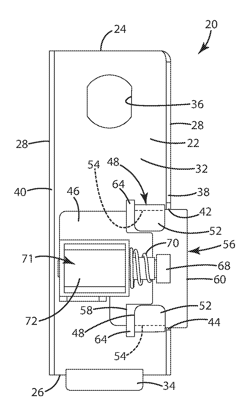
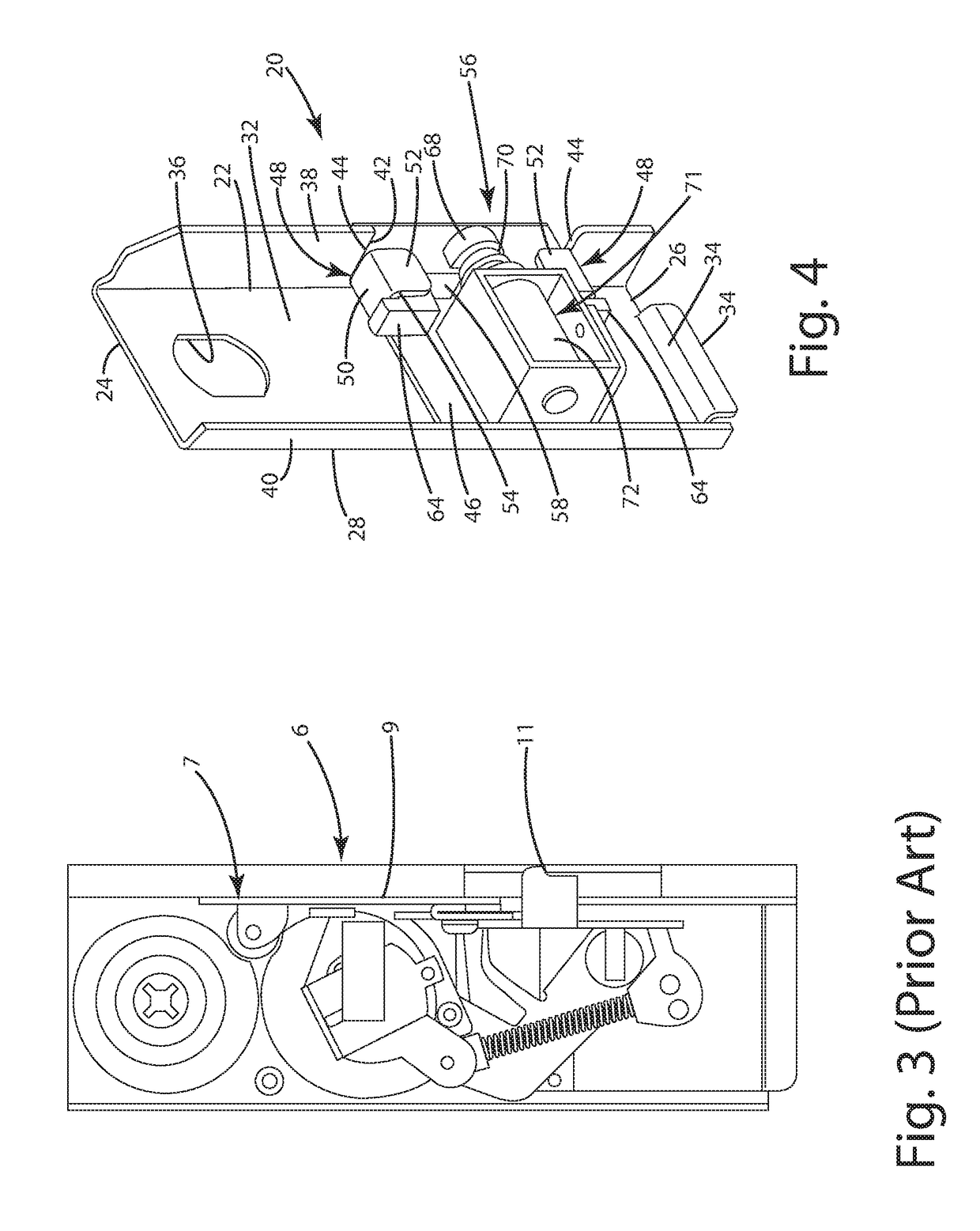
[0031]Referring to the Figures, wherein like numerals indicate corresponding parts throughout the several views, a modular electronic lock assembly 20 for a locker system 12 is generally shown for being received by an opening or slot 4 in a frame 1, such as the illustrated face frame, of a cabinet 2.

[0032]The modular electronic lock assembly 20 includes a mounting plate 22 that generally extends between a top edge 24 and bottom edge 26 along a pair of side edges 28. The mounting plate 22 of the present invention is generally rectangular shaped, however other shapes could be used, but the mounting plate 22 generally matches the shape of the mounting plate of the removed mechanical lock. The modular lock assembly 20 is generally formed out of modular parts that are easily replaced or substituted to fit other sizes or shapes, or even other functionality. The mounting plate 22 also presents a front face 30 and a back face 32. The lock assembly 20, particularly the mounting plate 22, is ...


PUM


Abstract

A modular lock assembly for placement in an opening in a frame of a cabinet locker that is located adjacent to a door of the cabinet locker. The modular lock assembly includes a mounting plate for removeably being positioned in the opening. A locking plate is moveably connected to the mounting plate. An electromechanical actuator is connected to the mounting plate and coupled with the locking plate to automatically provide the movement of the locking plate. An input device is electrically connected to the electromechanical actuator for activating the electromechanical actuator in response to inputs. The mounting plate defines a custodian opening for receiving a custodian lock for locking the mounting plate to the frame. At least one tongue extends from the mounting plate in spaced relationship with the custodian opening for engaging the frame for further securing the mounting plate to the frame.

Description

CROSS-REFERENCE TO RELATED APPLICATIONS[0001]This U.S. patent claims the benefit of U.S. Provisional Patent Application Ser. No. 62 / 256,337 filed Nov. 17, 2015, entitled “Modular Lock System,” the entire disclosure of the application being considered part of the disclosure of this application and hereby incorporated by reference.TECHNICAL FIELD[0002]A modular lock system for locker systems. More specifically, a modular electronic lock assembly for locking cabinet locker systems, such as rental lockers, and a modular electronic lock system configured to easily replace mechanical or keyed locks, and retain certain functionality while minimizing changes to the existing locker system.BACKGROUND OF THE DISCLOSURE[0003]Coin and key operated cabinet locker systems are known in the art for allowing users to securely store items and are commonly seen in train stations, sporting venues, ski slopes gyms, evidence lockers, and any other type of location or facility where it is desired to secure...

Claims


Application Information

Patent Timeline
IPC IPC(8): E05B65/02G07F17/12E05B47/00E05B37/16E05B35/14E05B63/00
CPCE05B65/025E05B35/14E05B63/00E05B2047/0091E05B37/16G07F17/12E05B47/0004E05B9/08E05B47/026
Inventor FRANK, DAVID SCOTTNOHR, DANIELRODRIGUEZ, EFRAIN
Owner CKI LOCKER LLC
Why Eureka
Try Eureka