Fault detection method and mobile wireless system

a technology of fault detection and mobile wireless system, which is applied in the direction of receiving monitoring, data switching network, transmission monitoring, etc., can solve the problems of huge cost and a very long tim

Active Publication Date: 2017-05-25
NEC CORP
View PDF0 Cites 15 Cited by
  • Summary
  • Abstract
  • Description
  • Claims
  • Application Information

AI Technical Summary

Benefits of technology

[0014]By using the present invention, a failure or a fault in a wireless facility can be detected and a fault location can be identified by using for example, a mobile body in service without stopping the operation of the mobile body.

Problems solved by technology

However, in order to detect a failure or a fault in these devices and identify a fault location, in general, it is required to perform an on-site investigation and it takes a huge cost and a very long time.

Method used


Image

  • Fault detection method and mobile wireless system
  • Fault detection method and mobile wireless system
  • Fault detection method and mobile wireless system

Examples


first example embodiment

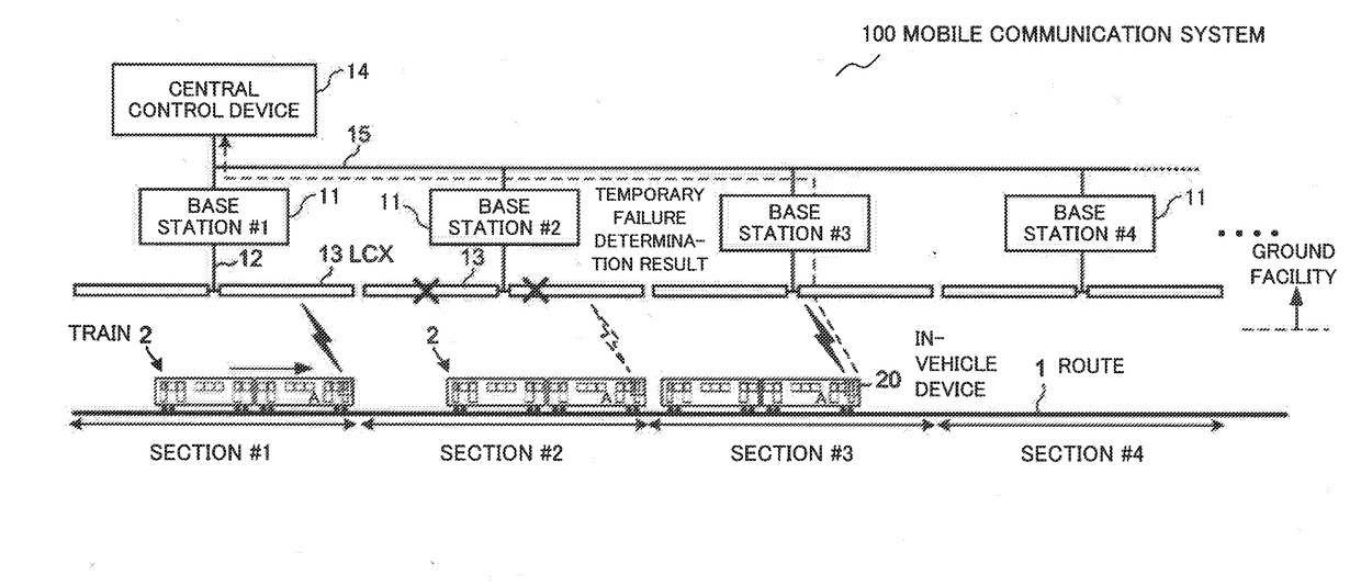
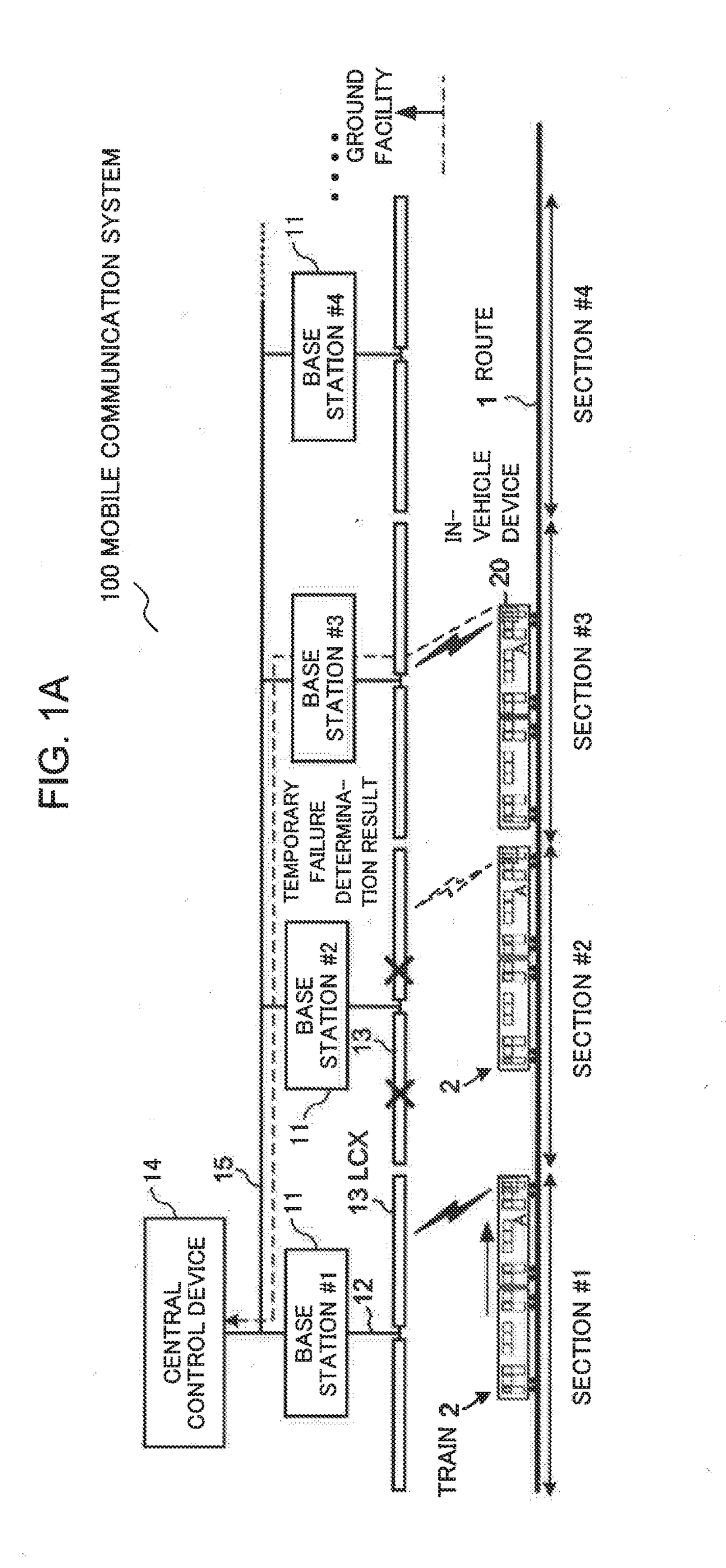
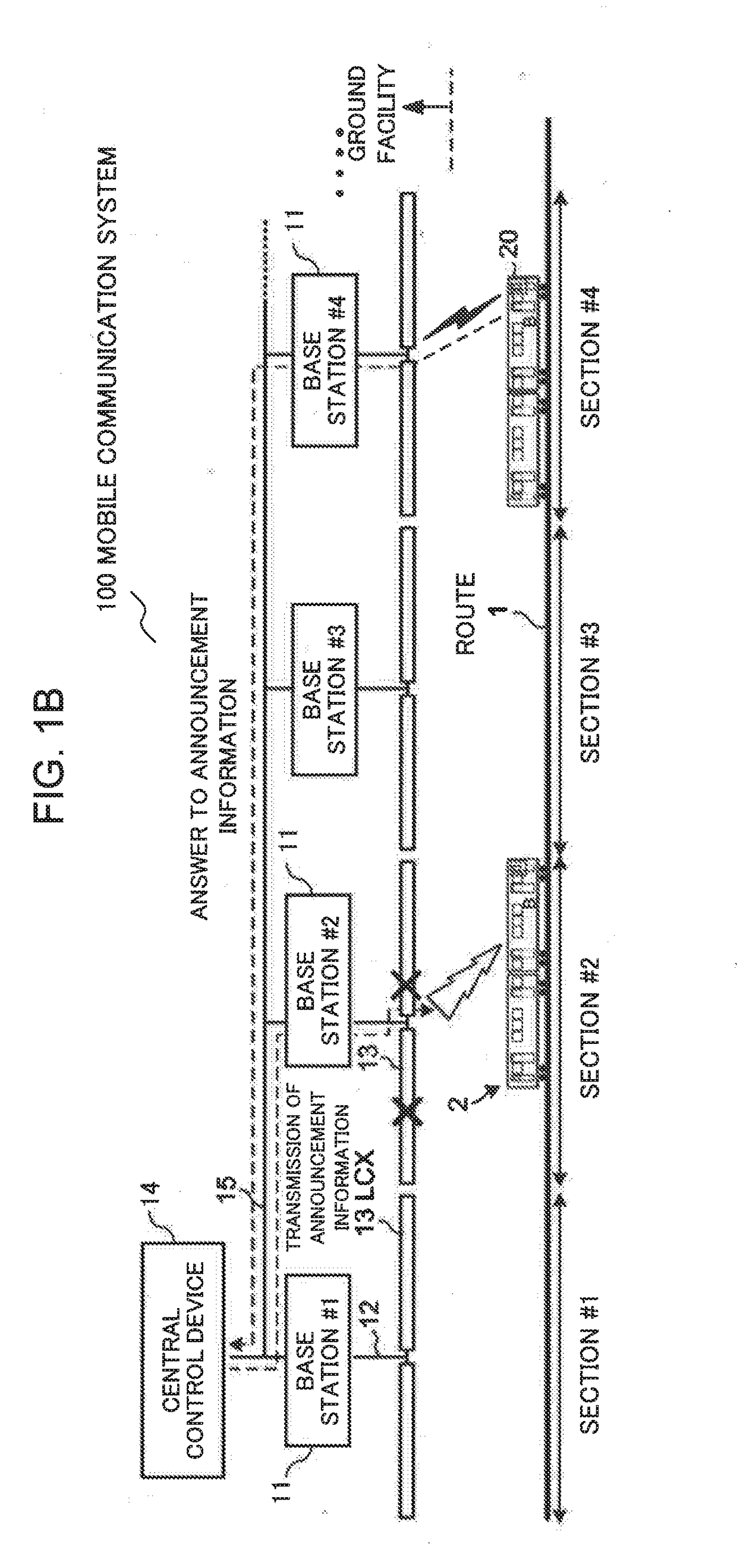
[0024](First example embodiment) FIG. 1A and FIG. 1B illustrate a mobile communication system according to the present invention and show a configuration of a mobile communication system 100 according to the first example embodiment. Further, FIG. 1A shows the operation of a temporary failure determination described later and FIG. 1B shows the operation of a final failure determination. Here, a route 1 represents a railroad and for example, a train 2 travels on the railroad track of the route 1 according to a predetermined train operation schedule (in other words, a train operation diagram) and wireless communication is performed with the train 2 on the route 1. Accordingly, the mobile communication system 100 is configured as a train radio system in which the mobile body is a train. Of course, the mobile communication system 100 can be configured as another system other than the train radio system in which the mobile body is a train traveling on the railroad tracks. For example, th...


PUM


Abstract

In order to identify a fault location, a fault detection method in which a base station installed in each of a plurality of sections of a route, an antenna which is connected to the base station and installed along the route, and a control device which controls all the base stations installed along the route are used comprises: measuring a strength of a signal emitted from the antenna in at least one mobile body in operation; acquiring a temporary failure determination result based on the signal strength, transmitting announcement information by the control device via the base station and the antenna to which it is determined that a failure occurs when the temporary failure determination result is acquired, transmitting an answer to the control device by the arbitrary mobile body in operation and receives the announcement information, and making a final failure determination based on the answer transmitted from each mobile body in the control device.

Description

TECHNICAL FIELD[0001]The present invention relates to a technology for detecting a failure or a fault in a wireless facility. In particular, the present invention relates to a fault detection method for identifying a fault location in a wireless facility which performs wireless communication with a mobile body such as a vehicle or the like, a mobile wireless communication system which can perform the fault detection method, and an in-vehicle device and a control device of which such mobile wireless system is composed.BACKGROUND ART[0002]In order to enable wireless communication between a train which travels on a railroad track and a ground facility (for example, an operation command room), a train radio system which is one kind of a mobile communication system is provided. The railroad track can be regarded as one line (in a case in which it is required to distinguish two lines in both directions in a double track section, two closed lines) when it is seen in broad perspective. Acco...

Claims


Application Information

Patent Timeline
Patent Type & Authority Applications(United States)
IPC IPC(8): H04L12/24H04W24/10H04W24/08B61L15/00B61L27/00H04W4/02H04W4/46
CPCH04L41/0677B61L15/0027B61L27/0005H04W88/08H04W24/10B61L2205/00H04W24/08B61L3/12B61L15/0081H04B5/0018H04W24/04H04B17/17H04B17/26H04B17/318H04W4/46H04W4/02B61L27/53B61L27/20B61L27/70
Inventor KOJIMA, TAKASHI
Owner NEC CORP
Why Eureka
Try Eureka