
Power supply control circuit, electronic device, and printing apparatus

a technology of power supply control circuit and control circuit, which is applied in the direction of process and machine control, instruments, printing, etc., can solve problems such as typical failure of power supply outpu

Inactive Publication Date: 2007-04-12
CANON KK
View PDF5 Cites 15 Cited by
  • Summary
  • Abstract
  • Description
  • Claims
  • Application Information

AI Technical Summary

Benefits of technology

[0012] In view of the above problems in the conventional art, the present invention has an object to allow detecting a failure in a power supply device having a DC / DC converter regardless of the start-up state of the DC / DC converter.

Problems solved by technology

Driving of the equipment upon generation of a state such as an overvoltage in the power supply may deteriorate a driven portion or cause a failure.
The above-mentioned overvoltage is a typical failure of the power supply output.

Method used


Image

  • Power supply control circuit, electronic device, and printing apparatus
  • Power supply control circuit, electronic device, and printing apparatus
  • Power supply control circuit, electronic device, and printing apparatus

Examples


Embodiment Construction

[0023] Preferred embodiments of the present invention will be described in detail in accordance with the accompanying drawings. The present invention is not limited by the disclosure of the embodiments and all combinations of the features described in the embodiments are not always indispensable to solving means of the present invention.

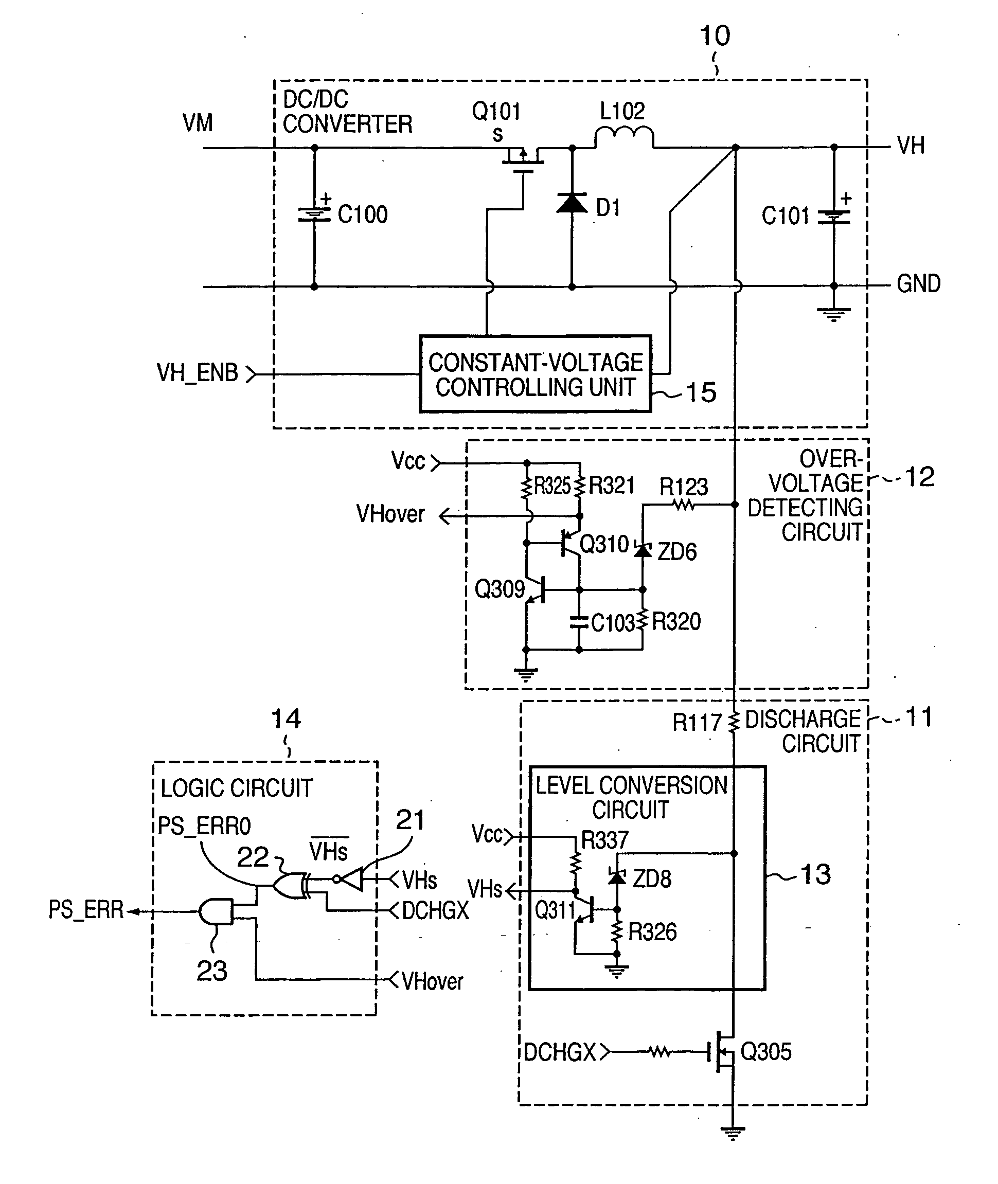
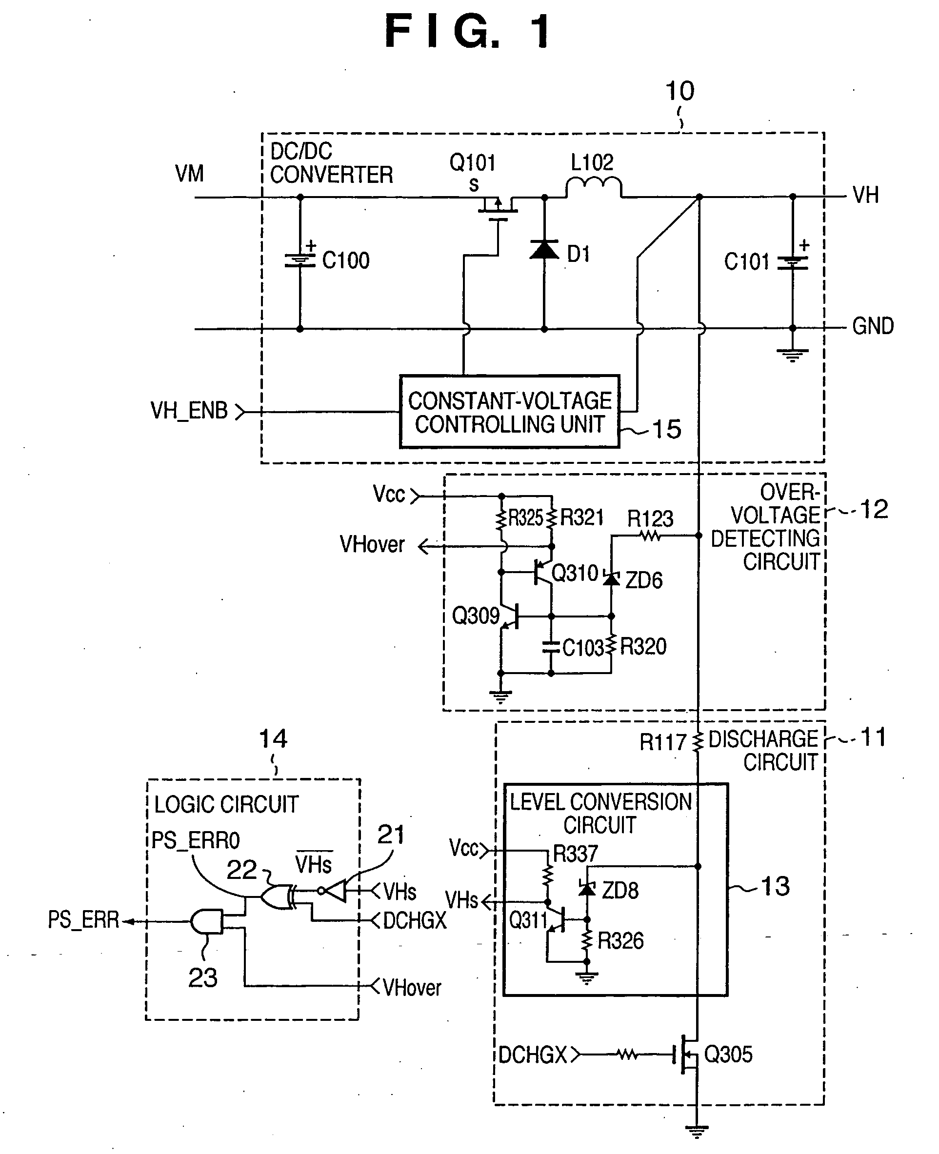
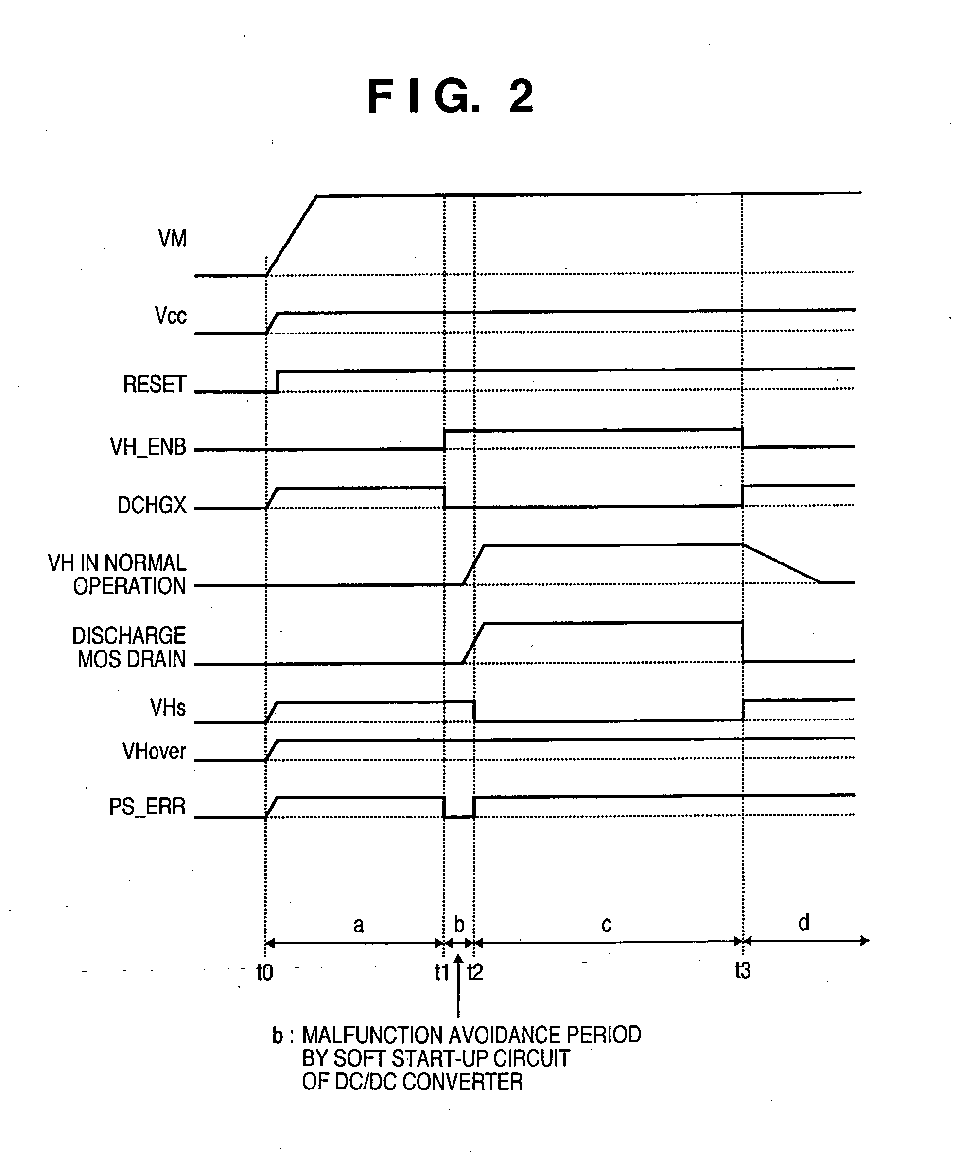
[0024]FIG. 1 is a circuit diagram showing a power supply control circuit according to the embodiment of the present invention. The power supply control circuit in the embodiment comprises, as a power supply circuit, a DC / DC converter 10 which converts an input DC voltage into a desired DC voltage. The power supply control circuit also comprises an overvoltage detecting circuit 12 which detects that the output voltage of the DC / DC converter 10 reaches a predetermined voltage or more, a discharge circuit 11 which removes charges accumulated in the output capacitor of the DC / DC converter, and a logic circuit (error detecting circuit for the power suppl...


PUM


Abstract

A power supply control circuit for controlling a power supply circuit having a DC / DC converter is provided. A discharge circuit operates based on a discharge instruction signal for instructing discharge and uses a switching element to remove charges of a capacitor connected to an output terminal of the DC / DC Converter. An overvoltage detecting circuit outputs a detection signal when a potential at the output terminal of the DC / DC converter exceeds a predetermined potential. A level conversion circuit outputs a signal obtained by converting a potential applied to the switching element of the discharge circuit. A logic circuit performs a logic operation between an inverted signal of a start-up signal, the detection signal, and the signal obtained by converting the potential, and outputs a failure detection signal representing a failed state of the power supply circuit.

Description

BACKGROUND OF THE INVENTION [0001] 1. Field of the Invention [0002] The present invention relates to a power supply control circuit, electronic device, and printing apparatus and, more specifically, to detection of a failure in a power supply circuit having a DC / DC converter. [0003] 2. Description of the Related Art [0004] In general, OA equipment having a mechanical part, such as a copying machine or printer, requires at least two types of power supplies having different voltages: a power supply (power supply for generating logic voltages of, e.g., +5 V and +3.3 V) for a logic circuit system for controlling the equipment and a power supply (power supply for generating driving voltages of, e.g., +24 V and +20 V) for a mechanism driving system. [0005] Of the two types of power supplies, the power supply of the driving system must ensure safety for a serviceman and user in maintenance of a driving system component, and save power when the equipment stands by. To meet these requirement...

Claims


Application Information

Patent Timeline
Patent Type & Authority Applications(United States)
IPC IPC(8): B41J29/38
CPCB41J29/393
Inventor SATO, TAKASHI
Owner CANON KK
Learn More