Unlock instant, AI-driven research and patent intelligence for your innovation.

Wet dual multi-plate clutch with levers outside the wet chamber

a multi-plate clutch and lever technology, applied in the field of dual clutches, can solve the problems of constant expansion of clutch demands, negative consequences of changing operating points and clamping forces, and limited transmission torque while keeping the construction size the same, so as to achieve the effect of reducing the amount of modification effort and expense, and reducing the number of construction spa

Inactive Publication Date: 2017-06-01
SCHAEFFLER TECH AG & CO KG
View PDF0 Cites 2 Cited by
  • Summary
  • Abstract
  • Description
  • Claims
  • Application Information

AI Technical Summary

Benefits of technology

The present invention provides a wet dual clutch that can be easily adapted for existing dual clutch vehicles by making only minor modifications. The clutch is actuated by an outside lever mechanism and is enclosed in a sealed chamber. It has high torque capacity and is well-suited for transmitting high torque. This design is particularly useful for agricultural machines such as tractors. The clutch housing supports the lever mechanisms and the friction linings are designed as disk packs. The wet chamber housing rests against the clutch housing and is sealed with the clutch housing. This design ensures that a large volume of frictional heat can be absorbed and removed, and reduces the size and cost of the clutch.

Problems solved by technology

It is disadvantageous that in such known dry dual clutches the maximum thermal absorptive capacity of the clutches and the maximum thermal capacity of the clutch linings as a rule is quickly reachable, in particular when transmitting high torques.
Increasing the transmissible torque while keeping the construction size the same is therefore limited.
In the critical load range, high wear of the friction linings and a resulting change of the operating points and clamping forces is therefore the negative consequence.
Added to the problem situation described above is the fact that the average power of motor vehicles using dual clutches, for example tractors, and thus the demands on the clutches, are constantly growing.
Present-day tractor dual clutches have reached their performance limits in some cases, especially with regard to thermal demands.

Method used


Image

  • Wet dual multi-plate clutch with levers outside the wet chamber
  • Wet dual multi-plate clutch with levers outside the wet chamber
  • Wet dual multi-plate clutch with levers outside the wet chamber

Examples


Embodiment Construction

[0051]The figures are merely schematic in nature, and serve only to aid in understanding the present invention. The same elements are identified by the same reference numerals. Details of the different embodiments can be combined with one another.

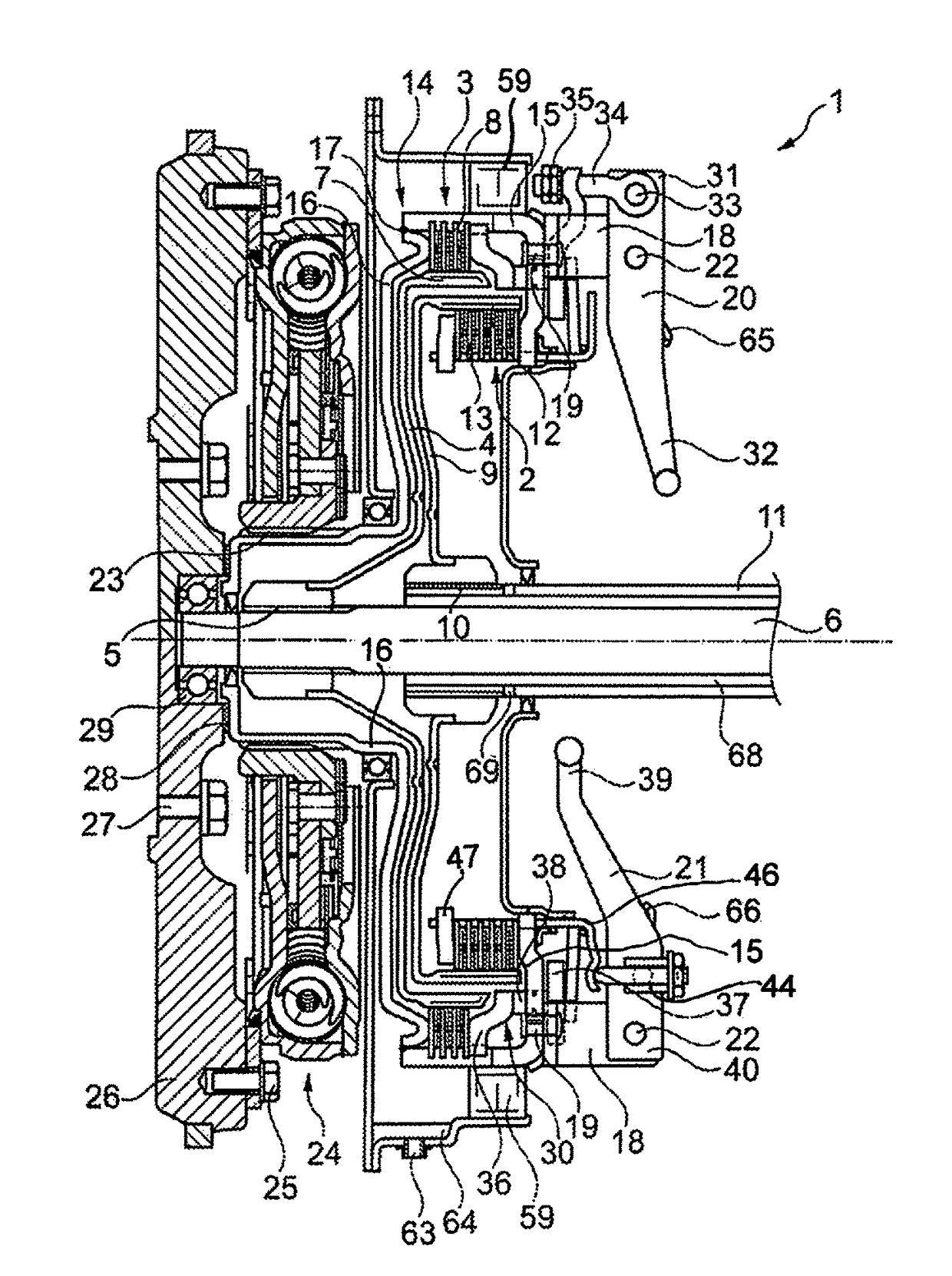
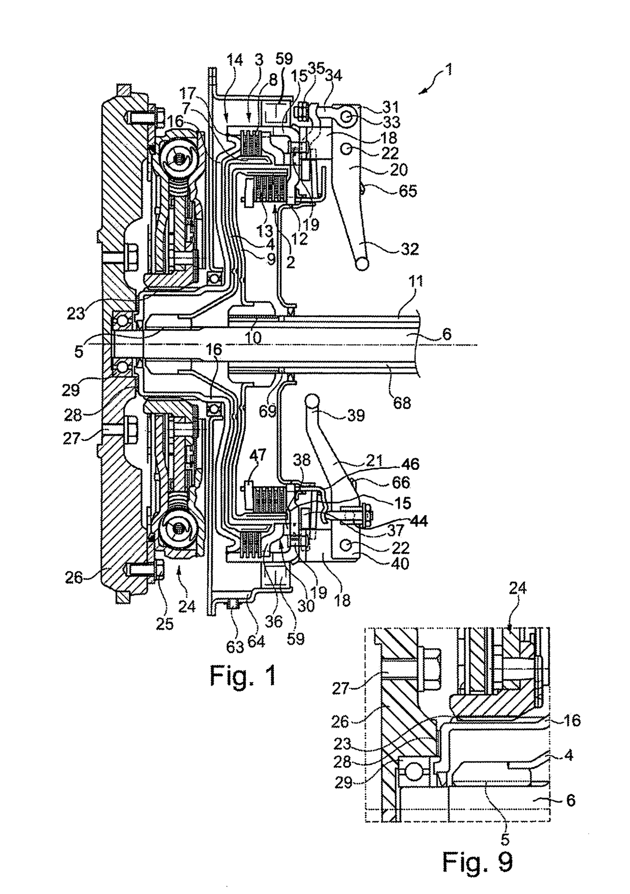
[0052]FIG. 1 shows a dual clutch 1 according to the present invention. It includes a first, radially inner clutch unit 2, in the present exemplary embodiment a drive shaft clutch 2, and a second, radially outer clutch unit 3, in the present exemplary embodiment a power take-off shaft clutch 3. The dual clutch 1 is designed as a wet clutch.

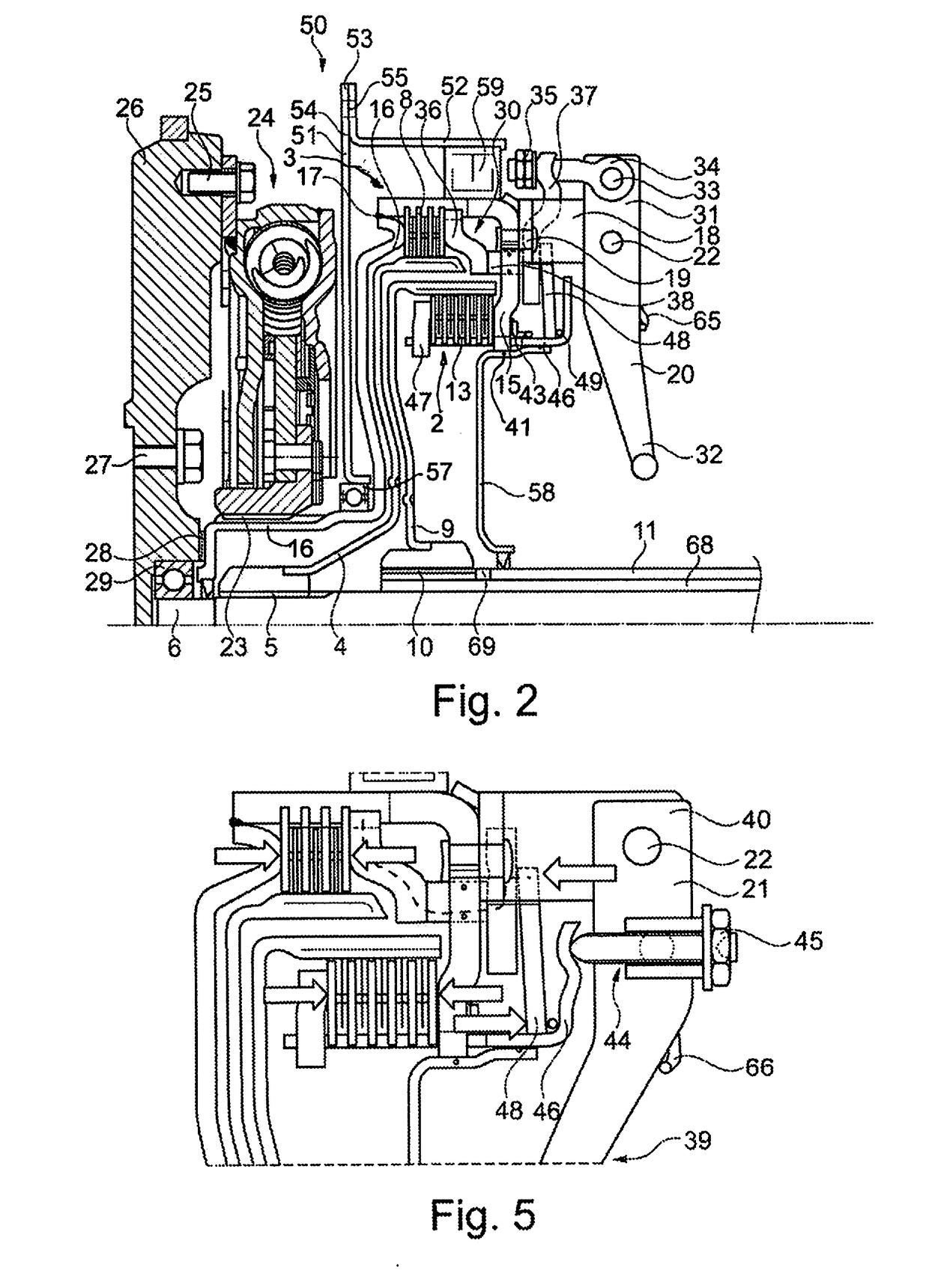
[0053]Referring to FIG. 2, power take-off shaft clutch 3 has a disk carrier 4, that is non-rotatably positioned on a power take-off shaft 6 by means of power take-off shaft toothed connection 5. The disk carrier 4 is an essentially bell-shaped formed sheet metal part, for example a deep drawn part, and carries a disk pack 8 on the outer side of its radially outer edge segment 7.

[0054]The drive shaft clutch...


PUM


Abstract

A multi-plate dual clutch for coupling a motor vehicle engine to a drive shaft of a motor vehicle transmission and to an auxiliary power take-off output shaft of the motor vehicle. The dual clutch includes a drive clutch for coupling the motor vehicle engine with the drive shaft, and an auxiliary power take-off clutch for coupling the motor vehicle engine with the auxiliary output shaft. The drive clutch and the auxiliary power take-off clutch can each to be operated independently of one another by a separate lever mechanism. The dual clutch includes a wet chamber housing in which the drive clutch and the auxiliary power take-off clutch are accommodated in fluid-tight relationship, while the respective lever mechanisms for the drive clutch and the auxiliary power take-off clutch are located outside the wet chamber housing.

Description

CROSS-REFERENCE TO RELATED APPLICATIONS[0001]This application is the U.S. national phase patent application under 35 U.S.C. ยง371 of International Patent Application Serial No. PCT / DE2015 / 200353, having an international filing date of 9 Jun. 2015, and designating the United States, which claims priority based upon German Patent Application No. DE 10 2014 212 421.2, filed on 27 Jun. 2014, the entire contents of each of which applications are hereby incorporated by reference herein to the same extent as if fully rewritten.BACKGROUND OF THE INVENTION[0002]Field of the Invention[0003]The present invention relates to a dual clutch, in particular a multi-plate dual clutch for coupling a drive shaft of a motor vehicle engine to a transmission shaft of a motor vehicle transmission and / or an auxiliary output shaft of an auxiliary power take-off of the motor vehicle, in particular a power take-off shaft. The dual clutch includes a drive clutch for coupling the motor vehicle engine with the tra...

Claims


Application Information

Patent Timeline
IPC IPC(8): F16D21/06F16D23/12F16D13/72F16D13/38F16D13/52
CPCF16D2021/0676F16D2300/26F16D2023/126F16D2300/08F16D23/12F16D13/385F16D13/52F16D13/72F16D21/06A01D69/08F16D2300/12
Inventor FILSINGER, ANDREASWEYDMANN, PATRICKGANDER, GERHARDOBITZ, ALEXANDER
Owner SCHAEFFLER TECH AG & CO KG