Electroactive polymer actuator

Inactive Publication Date: 2013-07-11
SIGNIFY HLDG BV
View PDF4 Cites 13 Cited by
  • Summary
  • Abstract
  • Description
  • Claims
  • Application Information

AI Technical Summary

Benefits of technology

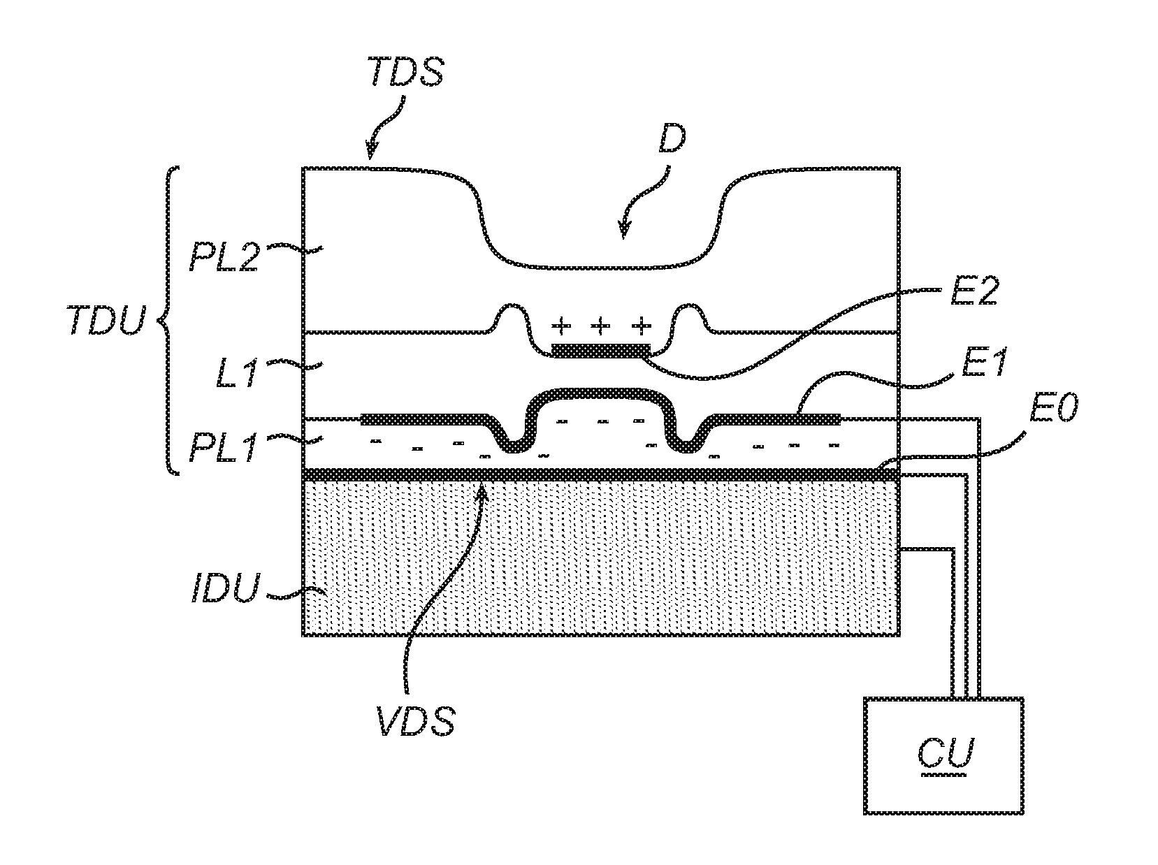
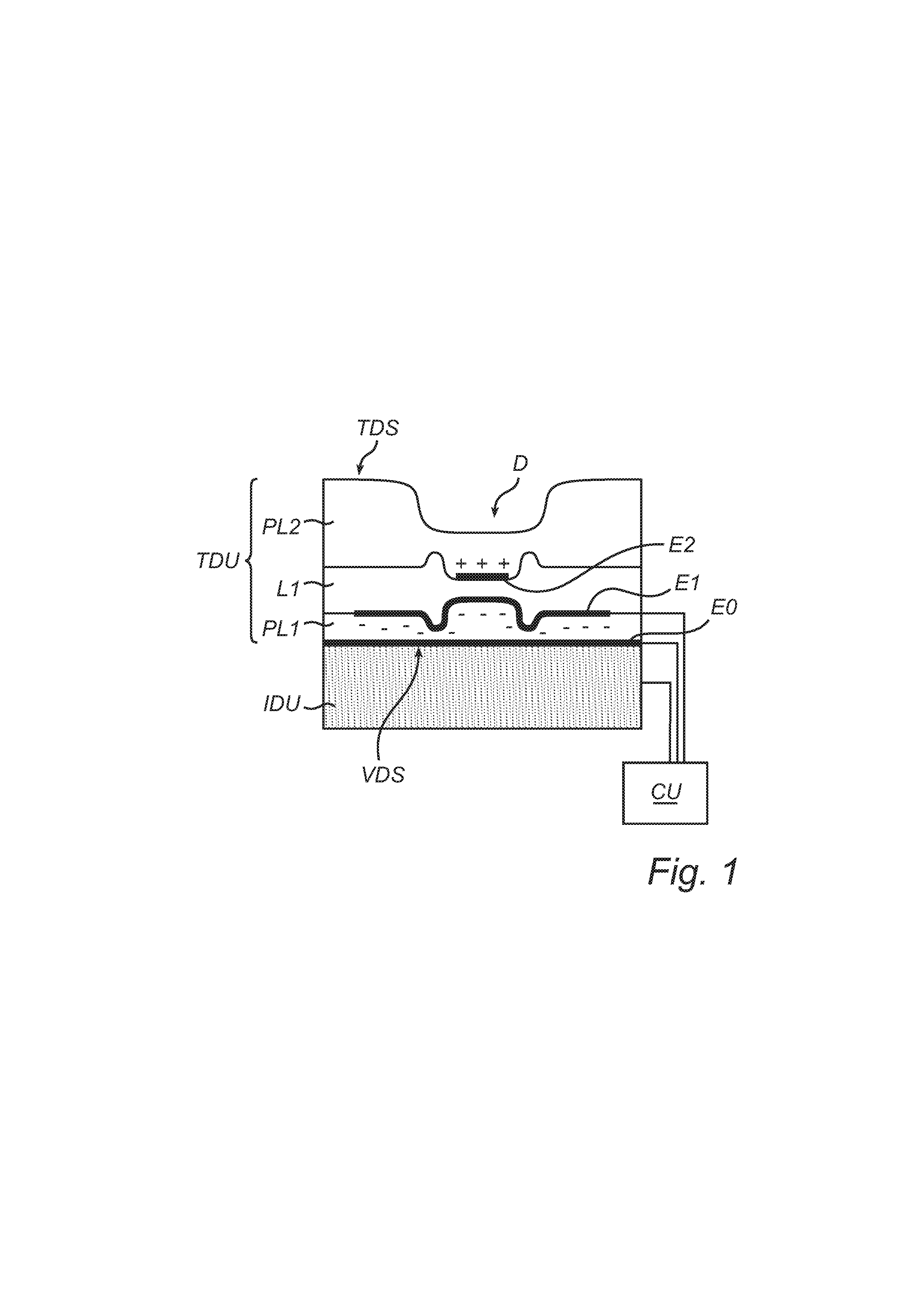
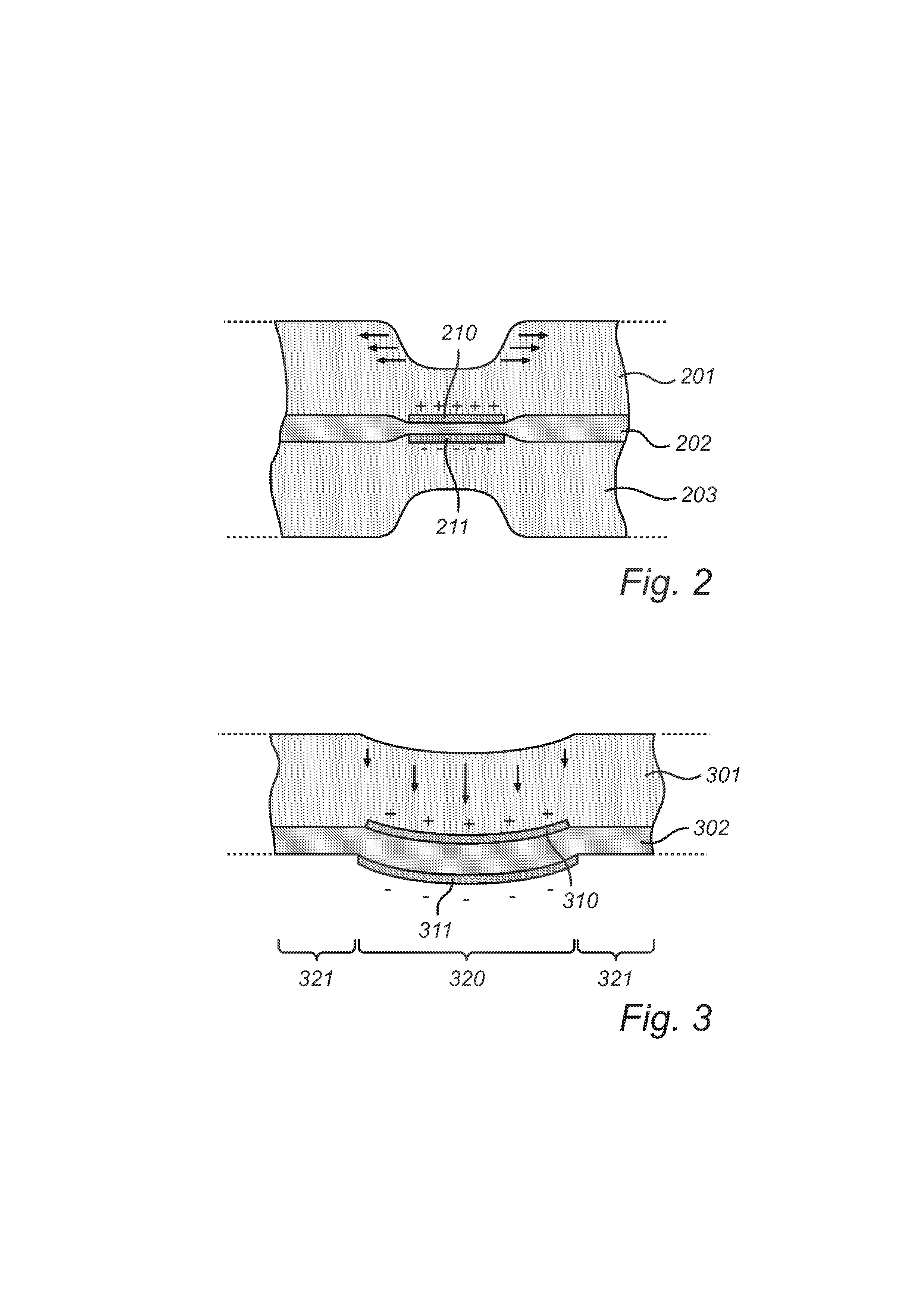
[0010]An advantage of the invention lies in that it produces a significant vertical amplitude (deep topography) at a small energy expense. This is because, in comparison with stretch-mode actuators with a thickness enhancement layer on a ‘user’ side, a smaller quantity of material is relocated. This is a consequence of the fact that the thickness enhancement layer in an actuated stretch-mode actuator is deformed into a configuration where it has smaller thickness than in the relaxed state. The two sides of the enhancement layer approach one another. In contrast, actuators according to the invention may create texture-enhancing edges by shifting a bounded region out-of-plane in substantially one single (transversal) direction; the two sides of the layer are displaced essentially parallel to one another. Thus, the invention achieves a comparable texture enhancement, at least from a tactile point of view, while operating at lower local stresses, so that the required peak voltage is lower and the life-cycle energy consumption is decreased. Also, larger deformations can be reached at the same voltage.
[0011]Another advantage of the invention, in comparison with actuators of the type disclosed in U.S. 2008/0289952, is that use of pre-strained actuator films is non-imperative. This simplifies the manufacture. Pre-straining favours stretch-mode deformation and accompanying formation of elevated edges rather than duck-mode deformation; for instance, pre-straining may contribute to a thickening of the EAP layer around the boundary of the active region.
[0012]Yet another advantage is t

Problems solved by technology

The material making up the elevated edge is supplied from the active area by stretching the latter into a thinner shape; such stretching may not be acceptable in all applications.
While actuators of this type may achieve a relatively large deflection amplitude, they are general

Method used


Image

  • Electroactive polymer actuator
  • Electroactive polymer actuator
  • Electroactive polymer actuator

Examples


example

[0063]Without being limited thereto, the invention will be illustrated by an example concerning an actuator of the type shown in FIGS. 4 and 5.

[0064]An EAP film in the form of a 80-μm layer of Nusil® CF19-2186 was made by doctor-blade coating on a suitable surface, e.g., a Teflon® plate. After curing in an oven, a well-performing dielectric actuation film was obtained. Secondly, a stretchable electrode was disposed on one side of the dielectric film. For the purposes of this application, “stretchable” particularly means that it can significantly change in length without significant material failures, such as mechanical rupture or loss of conductivity. In this example, the stretchable electrode was made of carbon black. On the other side of the dielectric film, aluminum-coated Mylar® foil of 1.5 μm thickness was deposited (draped) to serve both as the counter electrode and as a reflective surface. The Mylar® foil was applied with its reflective surface on the outside, as this gives a...


PUM


Abstract

An actuator comprises an electroactive polymer layer (402) and a stretchable electrode structure (403) disposed at a first side of the electroactive polymer layer and further a counter electrode layer (401) disposed on a second side of the electroactive polymer layer, wherein the ratio Yc/YEAP of the elastic modulus YC of the counter electrode layer and the elastic modulus YEAP of the electroactive polymer layer is at least 10. When compressed transversally by the electrodes, the electroactive polymer will expand tangentially and the actuator will relax into a shape wherein the interior of the electroded region is substantially recessed parallel to the plane of the device, while a substantial portion of the area increase is absorbed by out-of-plane bends arising at the electrode boundary (duck mode). The invention can be embodied as optically reflective or refractive devices with variable geometry.

Description

FIELD OF THE INVENTION[0001]The invention disclosed herein generally relates to electroactive polymer actuators. In particular, it relates to an actuator with an asymmetric layered structure, including one multifunctional electrode, with a capacity for localized out-of-plane actuation.[0002]The invention also relates to a method of manufacturing such an actuator.BACKGROUND OF THE INVENTION[0003]Dielectric actuators in the form of laminates (or sandwich structures or layered materials) belong to a rapidly evolving field of technology. A simple dielectric actuator may comprise a layer of electroactive polymer (EAP) and an electrode pair for applying an electrostatic force and thereby causing an elastic deformation of the polymer layer in the tangential (in-plane) and / or transversal (out-of-plane) direction. More sophisticated dielectric actuators may include additional functional layers, such as optically reflective or antireflective layers, texture-enhancing layers, electrically and / ...

Claims


Application Information

Patent Timeline
IPC IPC(8): H01L41/047
CPCG02B26/0825H01L41/047H01L41/193H01L41/0986H01L41/0478H10N30/87H10N30/878H10N30/206H10N30/857
Inventor BROKKEN, DIRKDE KONING, HENDRIKMARTAM, WENDY MIRELLECROMPVOETS, FLORIS MARIA HERMANSZVOGT, JUERGENVOSSEN, FRANK
Owner SIGNIFY HLDG BV
Why Eureka
Try Eureka