Half thrust bearing and bearing device for crankshaft of internal combustion engine

a technology of bearing device and crankshaft, which is applied in the direction of sliding contact bearings, mechanical equipment, rotary machine parts, etc., can solve the problems of easy damage (seizure), difficult to prevent the slide surface, and large vibration of the crankshaft, so as to reduce the weight of the internal combustion engine, reduce the shaft diameter of the crankshaft, and reduce the rigidity

Active Publication Date: 2017-06-15
DAIDO METAL CO LTD
View PDF0 Cites 10 Cited by
  • Summary
  • Abstract
  • Description
  • Claims
  • Application Information

AI Technical Summary

Benefits of technology

[0008]Further, in recent years, in order to reduce the weight of the internal combustion engines, shaft diameters of the crankshafts have been reduced, so that the crankshafts have lower rigidity than conventional crankshafts. Consequently, deflection easily occurs to the crankshafts at the time of operation of the internal combustion engines, and vibration of the crankshafts tends to become large. Accordingly, the slide surface of the half thrust bearing and a thrust collar surface of the crankshaft directly contact each other, so that damage (seizure) easily occurs.
[0011]In more detail, the half thrust bearing is used by being fitted to a bearing seat (seating face) which is provided in a cylinder block and a side surface of a bearing cap, and the inside diameter of the bearing seat is formed to be slightly larger than the outside diameter of the half thrust bearing, so that the half thrust bearing is movable slightly in the circumferential direction. When a pair of half thrust bearings are used by being combined into a ring shape (see FIG. 10 of JP-A-H11-201145, for example), the thrust collar surface of the crankshaft tends to contact the slide surface of one of the half thrust bearings first, instead of simultaneously contacting the slide surfaces of both the pair of half thrust bearings, at the instant when the axial force from the crankshaft is inputted to the slide surface of the thrust bearing. Consequently, the one of the half thrust bearings slightly moves in the circumferential direction with rotation of the thrust collar surface, and the circumferential end surface on the front side in the crankshaft rotational direction of the one of the half thrust bearings collides with the circumferential end surface on the rear side in the crankshaft rotational direction of the other half thrust bearing, and an impulsive load is repeatedly applied to the vicinities of the circumferential end surfaces of these half thrust bearings. Due to the influence of the impulsive load, fatigue (a crack and peeling from a steel back metal layer) easily occurs to the thrust relief adjacent to the circumferential end surface of the half thrust bearing or the bearing alloy layer on the slide surface which is adjacent to the thrust relief.
[0012]Accordingly, an object of the present invention is to provide a half thrust bearing for a crankshaft and a bearing device to which seizure and fatigue hardly occur at the time of operation of an internal combustion engine.

Problems solved by technology

Consequently, deflection easily occurs to the crankshafts at the time of operation of the internal combustion engines, and vibration of the crankshafts tends to become large.
Accordingly, the slide surface of the half thrust bearing and a thrust collar surface of the crankshaft directly contact each other, so that damage (seizure) easily occurs.
However, even when the art of JP-A-2001-323928 is adopted, if the vibration due to the deflection of the crankshaft described above is large, it is difficult to prevent the slide surface which is in proximity of the thrust relief on the rear side in a crankshaft rotational direction of the half thrust bearing from contacting the thrust collar of the crankshaft.
Consequently, seizure is likely to occur to the slide surface of the half thrust bearing.
Further, when the axial force which is inputted to the crankshaft by connection between the crankshaft and the transmission or the like is applied to the slide surface of the half thrust bearing, impulsive force is repeatedly applied to the vicinities of the circumferential end surfaces of the half thrust bearing, and therefore fatigue (a crack and peeling) may occur to the thrust relief or the bearing alloy on the slide surface which is adjacent to the thrust relief.
Due to the influence of the impulsive load, fatigue (a crack and peeling from a steel back metal layer) easily occurs to the thrust relief adjacent to the circumferential end surface of the half thrust bearing or the bearing alloy layer on the slide surface which is adjacent to the thrust relief.

Method used


Image

  • Half thrust bearing and bearing device for crankshaft of internal combustion engine
  • Half thrust bearing and bearing device for crankshaft of internal combustion engine
  • Half thrust bearing and bearing device for crankshaft of internal combustion engine

Examples


embodiment 1

(Entire Configuration of Bearing Device)

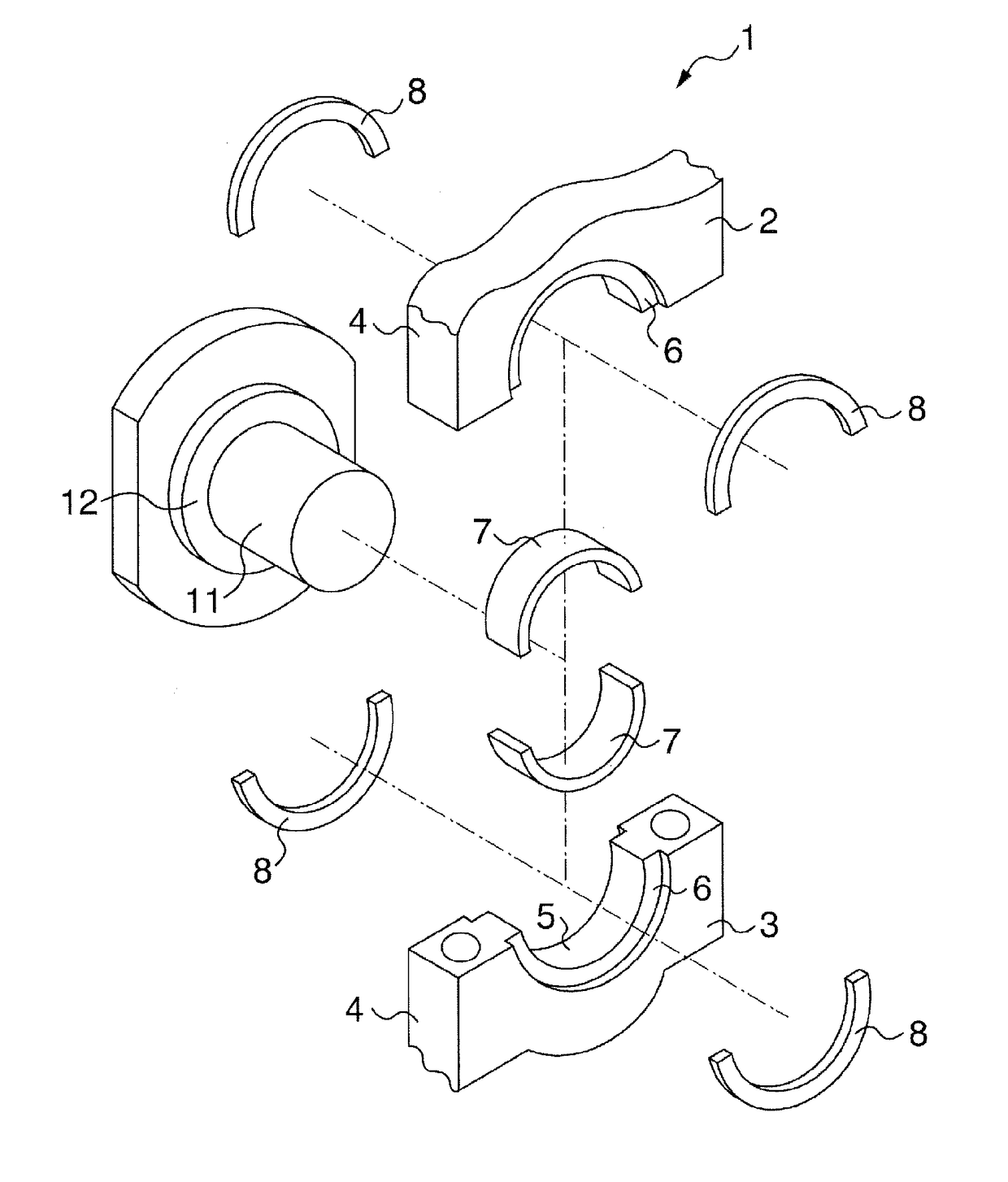
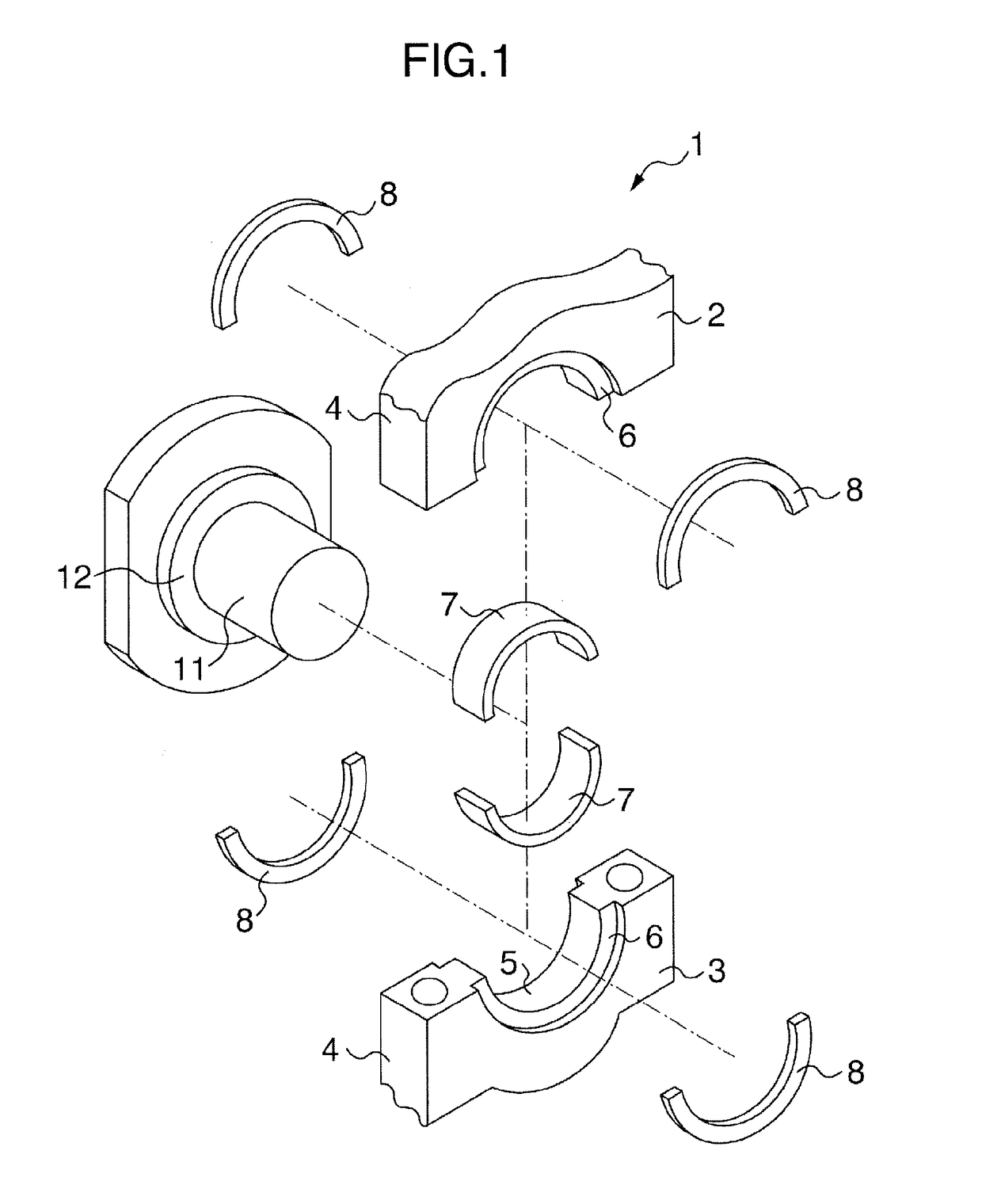
[0044]First, an entire configuration of a bearing device 1 of the present invention will be described with use of FIGS. 1 to 3. As illustrated in FIGS. 1 to 3, in a bearing housing 4 which is configured by mounting a bearing cap 3 onto a lower portion of a cylinder block 2, a bearing hole (holding hole) 5 which is a circular hole which penetrates between both side surfaces are formed, and bearing seats 6 and 6 which are ring-shaped recessed portions are formed on a circumferential edge of the bearing hole 5 on the side surface. Half bearings 7 and 7 which rotatably support a journal portion 11 of a crankshaft are combined into a cylindrical shape and are fitted in the bearing hole 5. Half thrust bearings 8 and 8 which receive force f (see FIG. 3) in an axial direction via a thrust collar 12 of the crankshaft are combined into a ring shape and are fitted to the bearing seats 6 and 6.

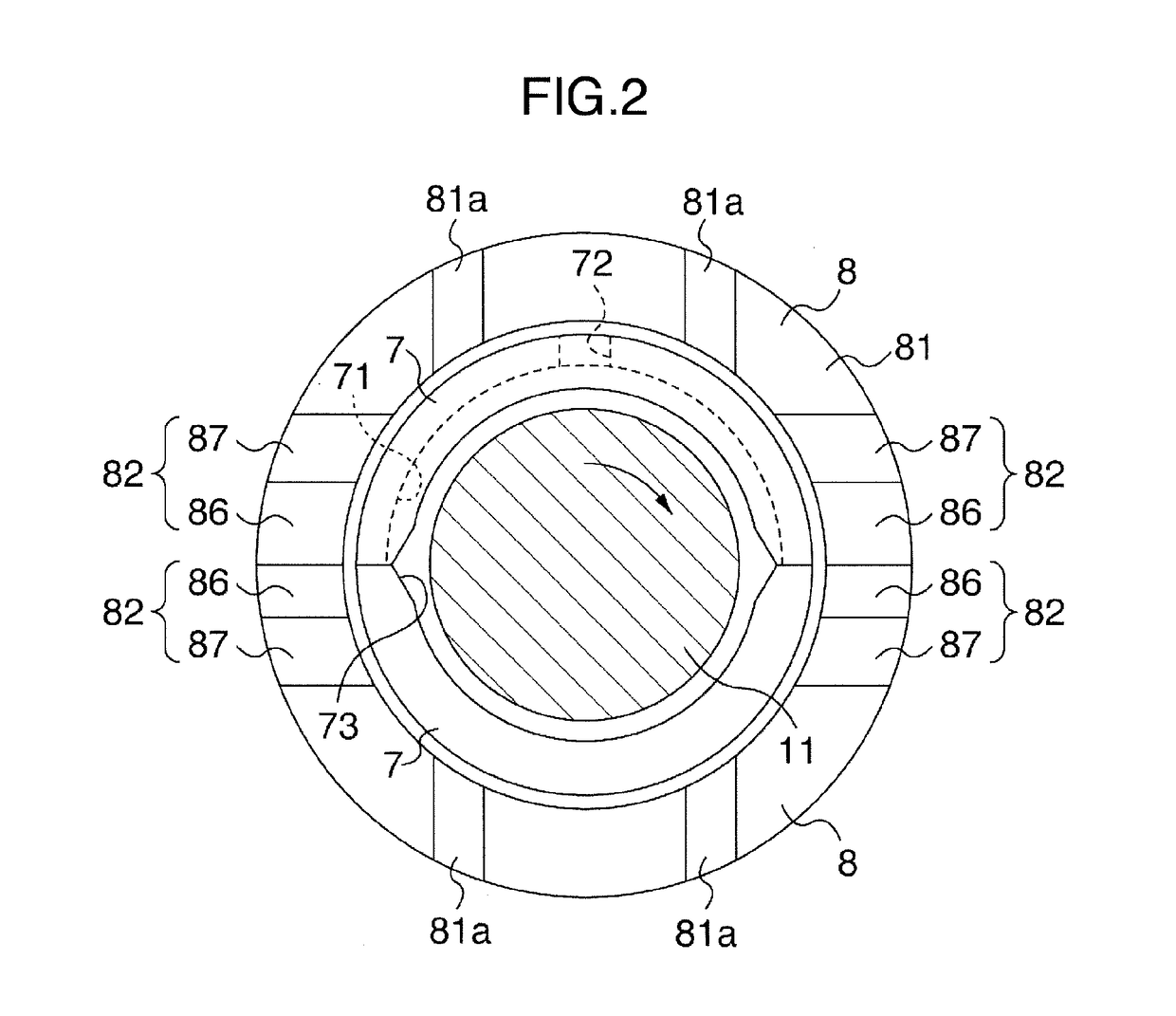
[0045]As illustrated in FIG. 2, a lubricating oil groove 71 is...


PUM


Abstract

There is provided a half thrust bearing having a semicircular-ring shape for a crankshaft of an internal combustion engine, including a back metal layer and a bearing alloy layer having a slide surface on which thrust reliefs are formed adjacently to both circumferential end surfaces so that a wall thickness of the half thrust bearing becomes thinner from the slide surface toward the circumferential end surfaces. A thrust relief length L1 of each thrust relief extends over a circumferential angle θ1 from the circumferential end surface toward a circumferential central portion, and is constant between an inside end portion and an outside end portion in a radial direction of the half thrust bearing. A flat surface of each thrust relief includes a first region on the circumferential end surface side and a second region on the circumferential central portion side.

Description

BACKGROUND OF THE INVENTION[0001]The present invention relates to a bearing device for receiving axial force of a crankshaft of an internal combustion engine.[0002]A crankshaft of an internal combustion engine is rotatably supported at its journal portion by a cylinder block lower portion of the internal combustion engine via a main bearing which is configured by combining a pair of half bearings into a cylindrical shape.[0003]One or both of the pair of half bearings are used by being combined with a half thrust bearing(s) which receives the axial force of the crankshaft. The half thrust bearing(s) is placed at one or both of axial end surfaces of the half bearing.[0004]The half thrust bearing receives the axial force which occurs to the crankshaft. That is, the half thrust bearing is disposed for the purpose of supporting the axial force which is inputted into the crankshaft when the crankshaft is connected with a transmission by a clutch or the like.[0005]On slide surface sides in...

Claims


Application Information

Patent Timeline
Patent Type & Authority Applications(United States)
IPC IPC(8): F16C9/02F16C33/12F16C17/10
CPCF16C9/02F16C17/10F16C33/122F16C2240/30F16C2360/22F16C17/04F16C33/046
Inventor TANAKA, SHIHOKOUSHIMA, MOTOHIKO
Owner DAIDO METAL CO LTD
Why Eureka
Try Eureka