Biopsy method and associated biopsy device

a biopsy method and biopsy sampler technology, applied in medical science, diagnostics, vaccination/ovulation diagnostics, etc., can solve the problems of reducing the accuracy of the biopsy method, and reducing the accuracy of the biopsy sampler, so as to maximize the safety

Active Publication Date: 2017-07-20
GENERAL ELECTRIC CO
View PDF2 Cites 3 Cited by
  • Summary
  • Abstract
  • Description
  • Claims
  • Application Information

AI Technical Summary

Benefits of technology

[0043]In an embodiment, said variable positioning of said biopsy volume is adapted so as to position said biopsy volume close to at least an edge of a breast

Problems solved by technology

However, these biopsy method technical problem and solution may be used for other organs of a human body.
This completely manual biopsy method moving manually the biopsy sampler does provide neither for sufficient precision nor for repeatability.
However, the unique fixed position of the biopsy volume relative to the breast support implies several constraints, at least part of them being relatively hard to get rid of.
A first problem of this second prior art deals with the fact that the fixed position of the biopsy volume leads to many breast manipulations by radiologist in order to check that the lesion is on the one side within the biopsy volume and on the other side at a place where the biopsy sampler can easily reach the lesion and perform the biopsy in the lesion.
This task is not easy and may become particularly difficult depending on the type of breast and on the place of the lesion within the breast.
A second problem of this second prior art deals with the extreme size of some breast which leads first to uncomfortable position of breast patient and/or second to a breast position which is not well maintained in the case of a breast lesion located near the nipple.
To be more precise, for small breasts w

Method used


Image

  • Biopsy method and associated biopsy device
  • Biopsy method and associated biopsy device
  • Biopsy method and associated biopsy device

Examples


first embodiment

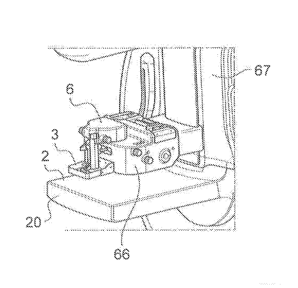
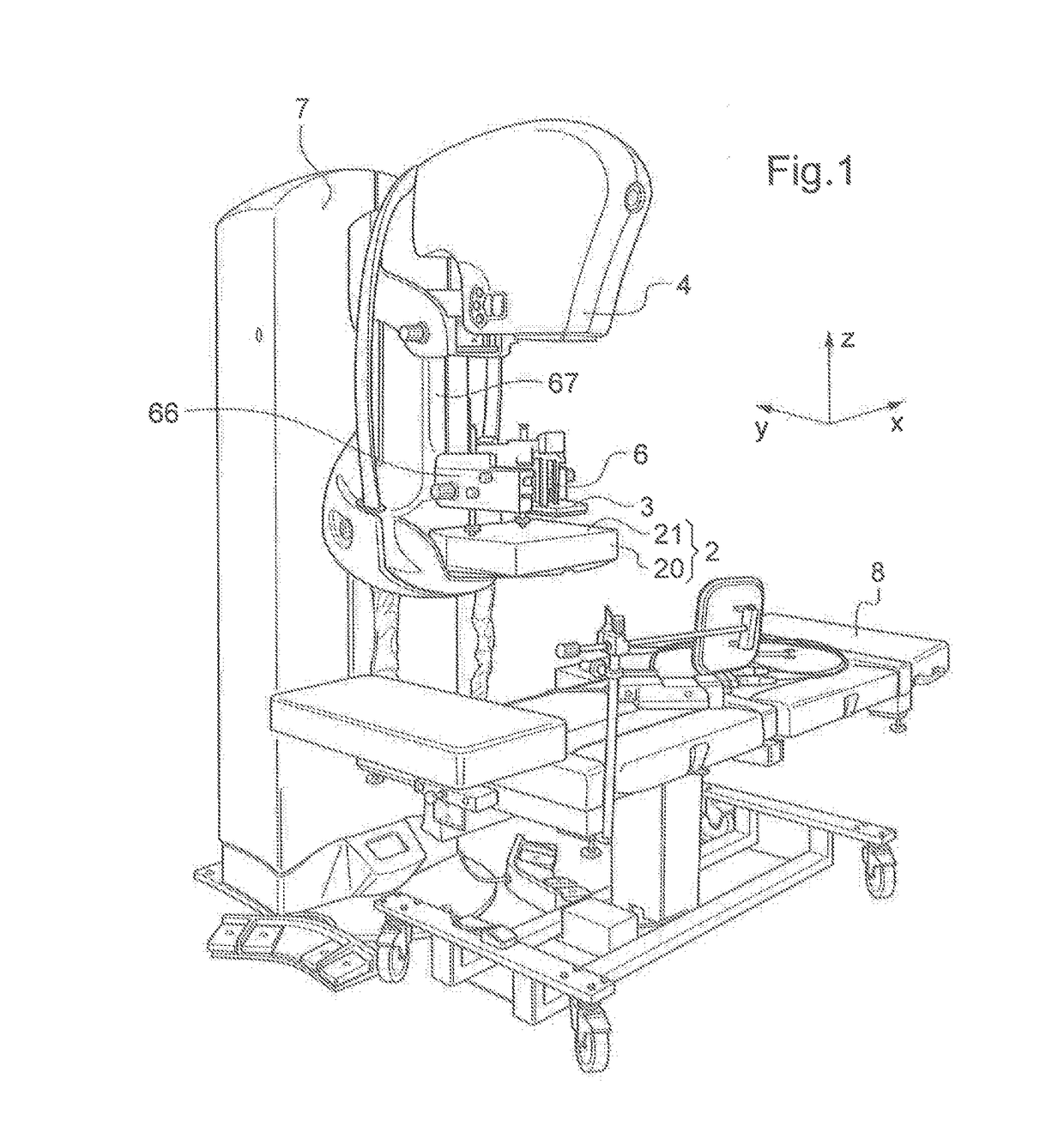
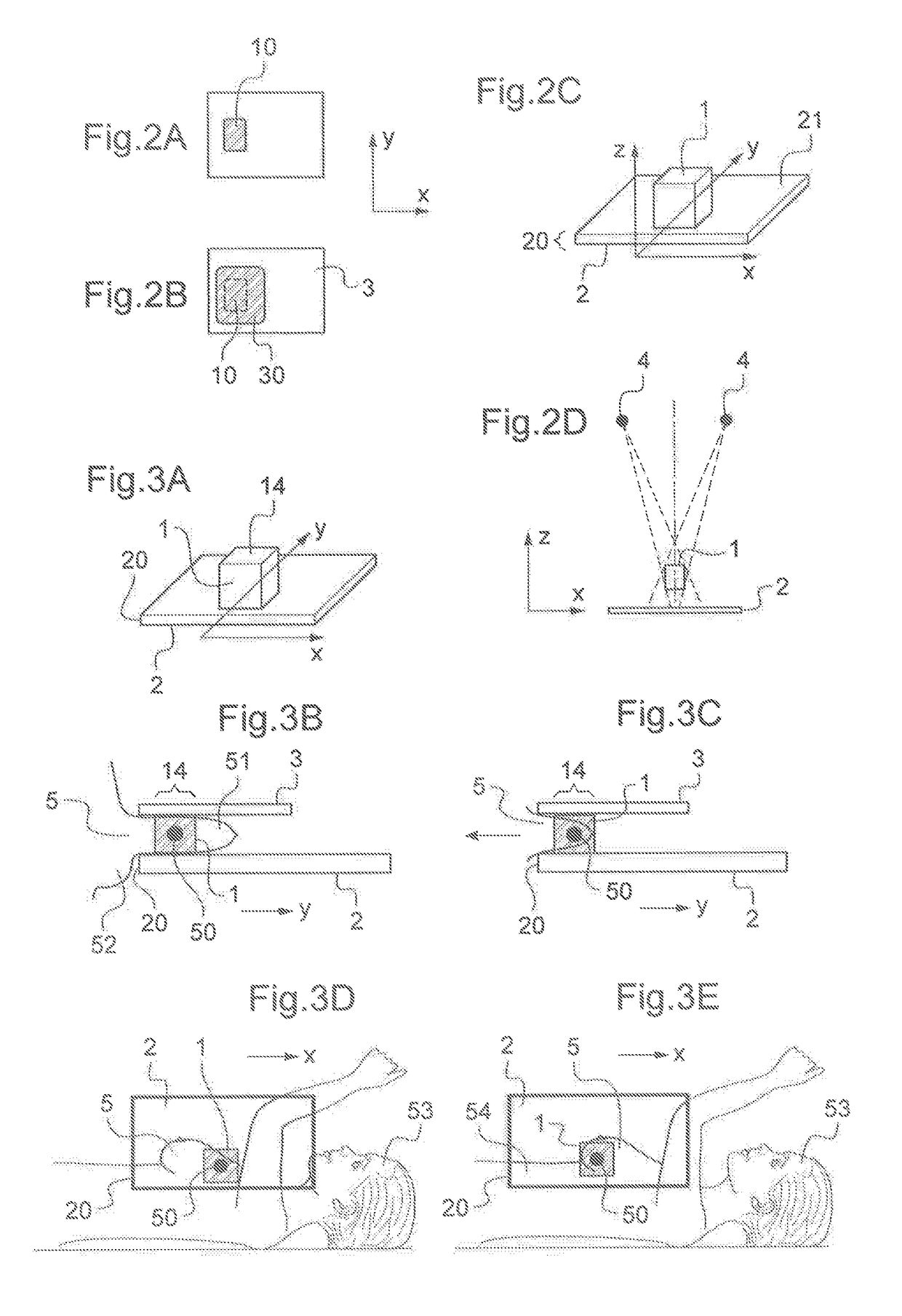
[0094]FIG. 6 shows a perspective view of an example of a biopsy mechanism used to perform the biopsy method according to the invention. The apparatus comprising the biopsy system includes an imaging system 67. A biopsy holder 66 is fixed relative to the detector 2 in the plane XY but is movable relative to detector 2 along the Z direction. The detector 2 is solidary attached with the imaging system 67. A biopsy sampler guide 6 is held by the biopsy holder 66. The biopsy sampler guide 6 may move relative to the biopsy holder 66, with translations of large extent, with respect to all directions X, Y and Z. It may also perform rotations. A paddle 3 is movingly, in the X,Y,Z directions in regards to detector 2, attached to a support 31. The support 31 is solidary attached with the imaging system 67, fixed in the plane XY of the detector 2 but is movable relative along the Z direction of the detector 2. The paddle 3 includes a hole 30. The space located between the hole 30 and the detect...

second embodiment

[0095]FIGS. 7A and 7B show perspective views of an example of a biopsy mechanism used to perform the biopsy method according to the invention. The apparatus comprising the biopsy system includes an imaging system. A biopsy holder 66 is attached with the imaging system 67. The biopsy holder 66 is movable relative to the detector 2 with translations of large extent, with respect to all directions X, Y and Z. A biopsy sampler guide 6 is held by the biopsy holder 66. The biopsy sampler guide 6 may move relative to the biopsy holder 66, with translations of limited extent, with respect to all directions X, Y and Z. It may also perform rotations. A paddle 3 is solidary fixed to the biopsy holder 66. The paddle 3 includes a hole 30. The space located between the hole 30 and the detector 2 constitutes the biopsy volume. The translational degrees of freedom of the block comprising biopsy holder 66 and paddle 3 in the plane XY relative to the detector 2 allows to displace the biopsy volume on...

third embodiment

[0096]FIG. 8 shows a perspective view of an example of a biopsy mechanism used to perform the biopsy method according to the invention. The apparatus comprising the biopsy system includes an imaging system 67. A biopsy holder 66 is attached with the imaging system 67. The biopsy holder 66 is movable relative to the detector 2 with translations of large extent, with respect to all directions X, Y and Z. A biopsy sampler guide 6 is held by the biopsy holder 66. The biopsy sampler guide 6 may move relative to the biopsy holder 66, with translations of large extent, with respect to all directions X, Y and Z. It may also perform rotations. A paddle 3 is movingly, in the plane XY, attached to a support 31. The support 31 is solidary attached with the imaging system 67 fixed in the plane XY of the detector 2 but is movable relative to the detector 2 along the Z direction. The paddle 3 includes a hole 30. The space located between the hole 30 and the detector 2 constitutes the biopsy volume...


PUM


Abstract

This invention relates to a biopsy method comprising automated moving of at least part of a biopsy sampler within a biopsy volume, to perform a biopsy in a zone of interest in a body, wherein said automated moving is preceded by variable positioning of said biopsy volume.

Description

CROSS-REFERENCE TO RELATED APPLICATIONS[0001]This application is a US PCT National Phase filing under 35 U.S.C. 371 of co-pending International Application No. PCT / IB2014 / 001528, filed May 28, 2014, which is incorporated herein by reference in its entirety.FIELD OF THE INVENTION[0002]The invention relates to biopsy methods and associated biopsy devices, used to perform a biopsy in a human body, preferably in the breast of a human body.BACKGROUND OF THE INVENTION[0003]The biopsy method technical problem and associated solution will be described in relation to breast biopsy in order to be more concrete and clearer. However, these biopsy method technical problem and solution may be used for other organs of a human body. They will be all the more interesting than the considered organ can be of a broadly varying size and all the more interesting than the considered organ can lead to many different patient positions depending on the part of the organ to be accessed by the biopsy device.[0...

Claims


Application Information

Patent Timeline
IPC IPC(8): A61B10/02A61B90/17A61B90/11
CPCA61B10/0233A61B90/17A61B90/11A61B2017/3409
Inventor VANCAMBERG, LAURENCEMULLER, SERGEPETER, GUILLAUMEHILL, MARCIA C.BOUDIER, AURELIEMOULIN, ROMAINTALAVERANO FUENTES, AURORA
Owner GENERAL ELECTRIC CO
Why Eureka
Try Eureka