Medical guide for guiding a medical instrument

a medical instrument and guide technology, applied in the direction of sensors, diagnostics, applications, etc., can solve the problem of minimal use, achieve the effect of minimizing patient discomfort, small and economical, and maximizing safety

Inactive Publication Date: 2008-08-21
APRIOMED
View PDF5 Cites 39 Cited by
  • Summary
  • Abstract
  • Description
  • Claims
  • Application Information

AI Technical Summary

Benefits of technology

[0008]A general object of the present invention is to provide a trajectory guide which can be used in a way that maximizes safety and minimizes patient discomfort during the intervention. Another object of the present invention is to provide a small and economical trajectory guide visible in magnetic resonance imaging and computed tomography for use in medical devices such as puncturing guides for biopsies and other surgical guides. A further object is to provide a method of using the trajectory guide to improve the accuracy when verifying the angle of entrance of a needle guide using magnetic resonance imaging or computed tomography prior to perforating the patient's skin and tissue.
[0009]Thus, an object is achieved by providing a specifically tailored trajectory guide as an aligning or guiding member of a medical device intended for introduction of instruments into the body of a patient. The trajectory guide is provided with at least one distal and one proximal marker visible in magnetic resonance imaging or computed tomography. These markers are of such a size and distance from each other that they can be used to determine that the trajectory guide is dependably aligned with the target tissue. This is achieved by providing a function which can be used to determine the accuracy of the trajectory guide.
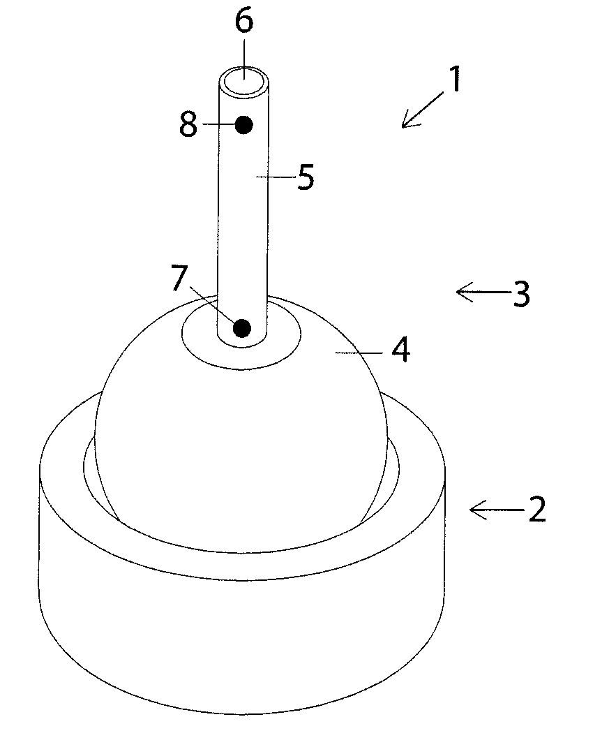
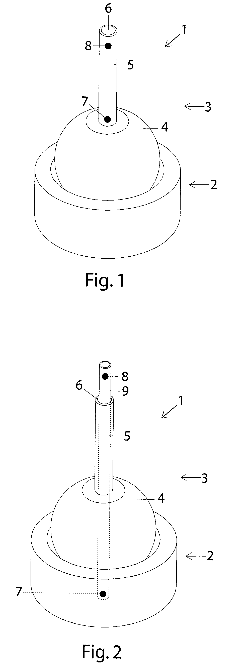
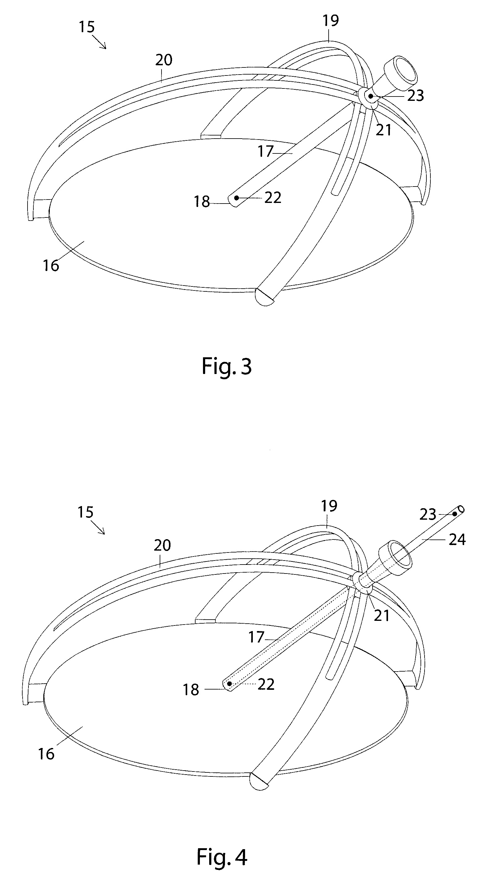
[0010]In a first embodiment the trajectory guide is provided as a hollow tube or instrument guide attached to a base which is attached or placed directly over the desired target tissue. The trajectory guide is freely angularly movable relative to the base and can therefore easily be aligned with the desired tissue site. In another embodiment, the trajectory guide is supplied as a separate member which can be attached to a trajectory guide having an instrument guide for a puncturing device, e.g. a biopsy needle. In a further embodiment, the trajectory guide is movable around a point that coincides with the defined puncturing entrance point. With such a puncturing guide, the tip of the puncturing device may be positioned at the puncturing point in a first operation and, in a subsequent operation; the entrance angle can be set without moving the position of the needle tip. In such an arrangement, the guide rod's distal marker is placed at the distal end of the rod, such that the distal tip of the guide rod is visible using magnetic resonance imaging and indicates the exact entrance point of the puncturing device.

Problems solved by technology

However, this puncturing guide is not visible in magnetic resonance imaging and is therefore of minimal use when planning the intervention with regards to optimizing the angle of the needle guide using magnetic resonance imaging.

Method used


Image

  • Medical guide for guiding a medical instrument
  • Medical guide for guiding a medical instrument
  • Medical guide for guiding a medical instrument

Examples


example 1

[0042]Given that

Lmin=t / (sin αmax)=t / (sin(arctan (R / D)))   (1)

a length between two markers on a trajectory guide of 10 cm, a lesion with a radius of 0.25 cm and a slice thickness of 0.2 cm, the lesion will be accurately targeted if it lies at a maximum depth of 12.5 cm.

example 2

[0043]If five different markers are used, with equal distance between each marker along a straight line, and given that

Lmin=t / (sin αmax)=t / (sin(arctan (R / D)))   (1)

a lesion with a radius of 0.25 cm and a slice thickness of 0.2 cm, the indicated markers visible in the image obtained in Table 1 correspond to a maximum depth (Dmax) where a lesion will be accurately targeted. Note that the markers are labeled m1 through m5, where m1 is the most distal marker (i.e. essentially at the entrance point of e.g. the biopsy guide) and m5 is the most proximal marker and the distance between m1 and m5 is equal to L.

TABLE 1Markers visible in imageDmaxDmax if L = 10 cmm10.25 * L2.5 cmm1, m2 0.5 * L5.0 cmm1, m2, m30.75 * L7.5 cmm1, m2, m3, m4 1.0 * L10.0 cm m1, m2, m3, m4, m51.25 * L12.5 cm 


PUM


Abstract

A medical guide (1, 15) is provided for guiding a medical instrument into a target site within a patient's body, for use in connection with a cross-sectional imaging technique such as magnetic resonance imaging or computed tomography. The medical guide comprises a base (2, 16) adapted to be positioned on the patient's body, a trajectory guide (5, 17) movably connected to the base, wherein the trajectory guide is provided with at least one distal marker (7, 22) and at least one proximal marker (8, 23) visible by said cross-sectional imaging technique, and the markers are separated by at least one portion not visible in a chosen cross-sectional imaging technique. Furthermore, the alignment markers are placed so as to optimize the trajectory path and facilitate the procedure of e.g. taking a biopsy sample using the selected cross-sectional imaging technique.

Description

FIELD OF THE INVENTION[0001]The present invention relates generally to a guide for guiding a medical instrument to a target site within a patient's body, and more particularly to a trajectory guide, visible using magnetic resonance imaging or x-ray based computed tomography (CT), for guiding a medical instrument, e.g. a biopsy instrument, to a target site, the position of which has been determined by means of magnetic resonance imaging or x-ray based computed tomography.BACKGROUND OF THE INVENTION[0002]Acquiring and providing diagnostic images of internal body structures and diseased or altered tissue is of great importance in many areas of medicine. Techniques to acquire such images include X-ray computed tomography (CT), ultrasonic imaging, emission tomography and magnetic resonance imaging (MRI). MRI and CT provide two-dimensional cross-sectional images through a patient, using magnetic fields and X-rays, respectively, visualizing internal structures in color or gray scale. These...

Claims


Application Information

Patent Timeline
Patent Type & Authority Applications(United States)
IPC IPC(8): A61B5/055A61B17/00
CPCA61B10/02A61B19/201A61B19/50A61B19/5244A61B19/54A61B2019/5454A61B2017/3407A61B2019/507A61B2019/5236A61B2019/524A61B2019/5287A61B2017/00911A61B2090/363A61B34/20A61B90/11A61B34/10A61B2034/107A61B2090/374A61B2090/3762A61B90/39A61B2090/3954
Inventor EKLUND, ANN-CHARLOTTETIENSUU, ANNA-LISANICKLASSON, EVA
Owner APRIOMED
Why Eureka
Try Eureka