
Method of controlling the switching of a multilevel converter, a controller for a multilevel converter, and a computer program for controlling a converter

a multi-level converter and controller technology, applied in the field of multi-level converters, can solve the problems of unsatisfactory balance of capacitor voltage levels, harmonic distortion, and unfavorable switching of switches, and achieve the effect of keeping the computational load at a low level

Active Publication Date: 2017-08-17
ABB POWER GRIDS SWITZERLAND AG
View PDF0 Cites 4 Cited by
  • Summary
  • Abstract
  • Description
  • Claims
  • Application Information

AI Technical Summary

Benefits of technology

The technical effects of this patent are to provide a method for controlling switching in a multilevel converter that is efficient and can handle a large number of levels. This is achieved by analyzing each switching cell separately, reducing the computational load. The method also ensures good balance of capacitor voltages, low switching loss, and a balanced loss distribution among the switching units.

Problems solved by technology

Such balancing may however create harmonic distortions.
However, using this modulation strategy does not necessarily provide a good balance of the capacitor voltage levels, and will also provide an unequal distribution of losses among the switches.
The control strategy of Zanchetta et al suffers from uneven balances of voltage levels of the capacitors (C), and an unbalanced loss distribution (D).
However, the loss distribution is not handled by this MPC strategy.
However, a problem with using MPC schemes, such as provided by Townsend, is that it requires many calculations in order to evaluate the cost functions.
However, the computational load has an exponential relationship to the number of voltage levels.
Therefore the computational load is typically infeasible in FACTS applications that uses more than 8-10 serially connected switching cells.

Method used


Image

  • Method of controlling the switching of a multilevel converter, a controller for a multilevel converter, and a computer program for controlling a converter
  • Method of controlling the switching of a multilevel converter, a controller for a multilevel converter, and a computer program for controlling a converter
  • Method of controlling the switching of a multilevel converter, a controller for a multilevel converter, and a computer program for controlling a converter

Examples


Embodiment Construction

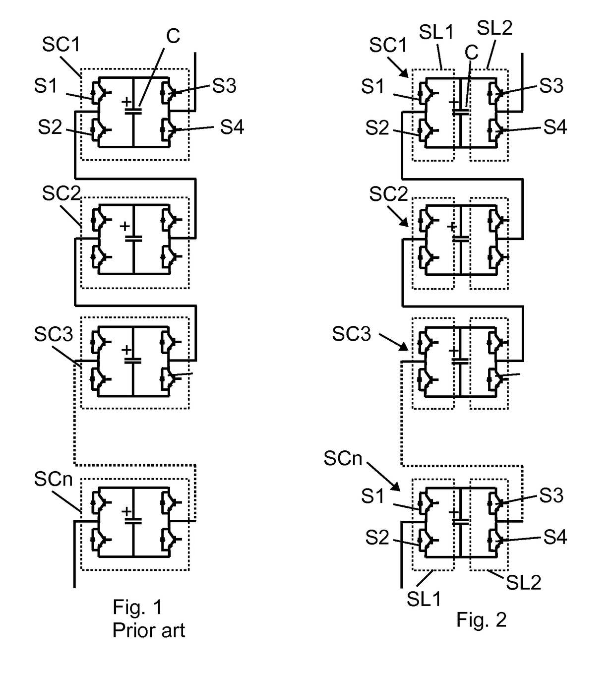
[0071]FIG. 1 illustrates a chain link in accordance with prior art comprising a number of serially connected H-bridge switching cells SC1, SC2, SC3, . . . , SCn, each comprising four switches S1, S2, S3, S4 in an H-bridge configuration with a capacitor C. In the prior art, the control of the connection of the capacitors for a control period includes an analysis being performed for each switching cell SC1-SCn, as indicated by dotted lines surrounding each switching cell SC1-SCn.

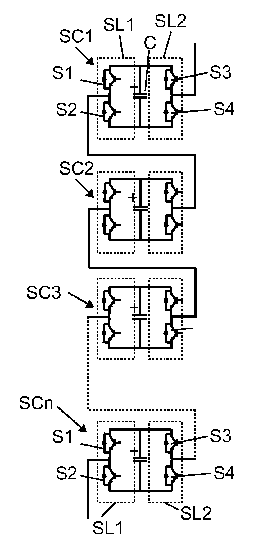
[0072]FIG. 2 illustrates a chain link in accordance with the invention. The configuration is the same as in the prior art. However, according to the invention, the analysis performed for controlling the connection of the capacitors C of the switching cells SC1-SCn is performed as two analysis for each switching cell SC1-SCn. One analysis is performed for a first switching leg SL1 of each switching cell SC1-SCn, and one analysis is performed on a second switching leg SL2 of each switching cell SC1-SCn. The anal...


PUM


Abstract

A method of controlling a multilevel converter, a computer program and a controller for a converter is provided. The method includes determining a transition voltage from a control period to a following control period, analyzing the switching cells of each phase leg, selecting capacitors to provide the transition voltage and synthesize the output voltage for the following control period, and connecting the selected capacitors during the following control period. The analyzing of each switching cell includes analyzing a first switching leg and a second switching leg of the switching cell. The method includes determining whether a change of state of the first switching leg would contribute to the direction of the transition voltage, and determining whether a change of state of the second switching leg would contribute to the direction of the transition voltage, and determining the internal conditions of each of the first and the second switching leg that are determined as contributing to the transition. Thus, the two legs of the H-bridge are analyzed separately. The selecting of capacitors is performed by selecting the capacitors of the switching legs of the phase leg for the transition voltage on the basis of the determined internal conditions of the switching legs, including comparing the internal conditions of all the switching legs of the phase leg. A controller is configured to control the multilevel converter by performing the method.

Description

TECHNICAL FIELD[0001]The invention relates to multilevel converters and especially to a method of controlling the switching of a multilevel converter.BACKGROUND AND PRIOR ART[0002]Multilevel converters are used in many high power applications for controlling active and reactive power at medium and high system voltages, such as in HVDC (High-Voltage, Direct[0003]Current) and FACTS (Flexible Alternating Current Transmission Systems) applications. A common multilevel converter comprises full-bridge switching cells, or H-bridges, each comprising four semiconductor switches and one capacitor, wherein the switching cells are arranged in chain links, one for each phase, and connected to the power system voltage via an inductor. The chain links are connected in a wye or delta configuration between the phases of the power system. FIG. 1 illustrates a chain link according to prior art comprising a number of switching cells SC1-SCn, each comprising four switches S1-S4 and a capacitor C.[0004]I...

Claims


Application Information

Patent Timeline
IPC IPC(8): H02M1/08
CPCH02M2001/0054H02M1/08H02M7/483Y02B70/10H02M1/0048H02M7/4835Y02E60/60H02M1/0054H02M3/33561
Inventor TOWNSEND, CHRISTOPHERZELAYA DE LA PARRA, HECTOR
Owner ABB POWER GRIDS SWITZERLAND AG
Learn More