Switched beam antenna system and hand held electronic device

a wireless short range communication and switch beam technology, applied in the field of low-cost handheld and portable wireless short range communication systems, can solve the problems of limited data rate, limited power as well as bandwidth, and limited broadband wireless transmission, and achieve the effect of short range communication

Inactive Publication Date: 2017-09-28
KING FAHD UNIVERSITY OF PETROLEUM AND MINERALS
View PDF0 Cites 9 Cited by
  • Summary
  • Abstract
  • Description
  • Claims
  • Application Information

AI Technical Summary

Problems solved by technology

Broadband wireless transmission is limited by the amount of power as well as the spectrum (bandwidth) allocated.
In current wireless standards, both the power as well as the bandwidth is limited to avoid interference and to serve multiple wireless transmissions for civil and military use.
Thus the achieved data rates have a limit.
Although multiple-input-multiple-output (MIMO) technology has been used to enhance the data rates using multiple antennas at the receiver and transmitter sides, very high data rates that can ensure true digital video and multimedia transfer are still a major throughput bottleneck to higher transmission rates.
Millimeter waves suffer from very high attenuation when used in wireless links due to several channel conditions, and this restricted their use to point-to-point links and military use.
The feeding structures of such arrays are also very challenging to design and optimize.

Method used


Image

  • Switched beam antenna system and hand held electronic device
  • Switched beam antenna system and hand held electronic device
  • Switched beam antenna system and hand held electronic device

Examples


Embodiment Construction

[0033]Referring now to the drawings, wherein like reference numerals designate identical or corresponding parts throughout the several views.

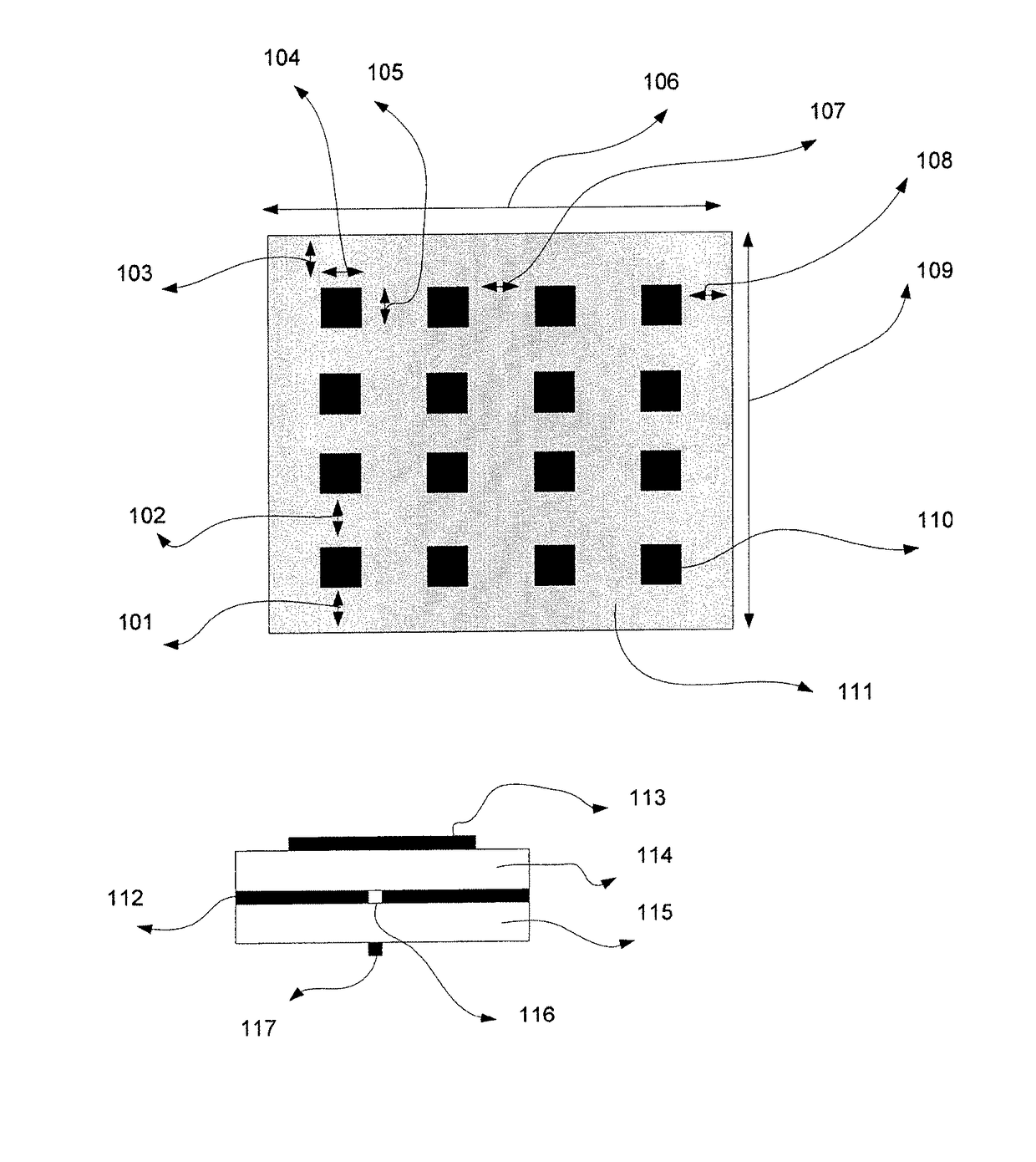
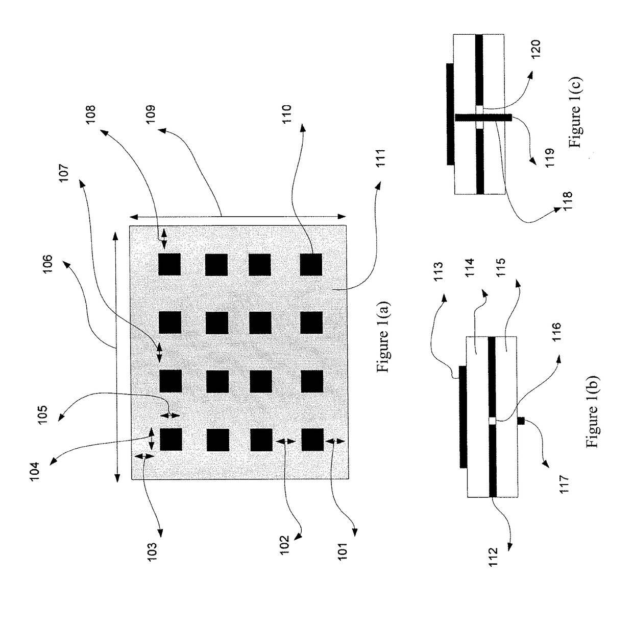
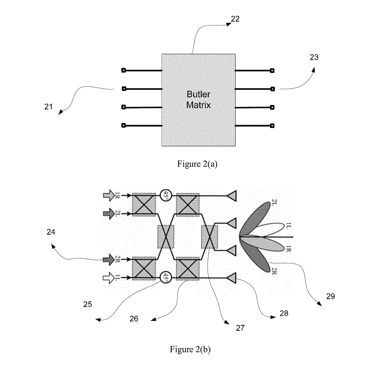
[0034]A switched mode antenna array for mm-wave frequencies targeting consumer electronic devices and short range communications is described. An specific example operating at a center frequency of 28.5 GHz is described. The antenna array includes printed antenna elements (i.e. patch or slot antennas) built on a low loss substrate that can withstand mm-wave frequency operation. In addition, the switched beam / mode operation may be provided via a specialized Butler Matrix feed network that is not feeding a single element per feed point but rather an array of elements. The integrated design consisting of the planar antenna array and the Butler Matrix is very compact and can fit within portable consumable electronic devices.

[0035]Multiple-Input-Multiple-Output capability can be utilized by integrating several arrays of this mm-wave switched design ...


PUM


Abstract

A mm-wave antenna apparatus with beam steering function that includes: a Butler Matrix feeding network; a plurality of power combiners, each power combiner having one input and N outputs, configured to apply equal phase and power to a phase distributed output signal generated by the Butler Matrix feeding network and to generate N processed signals; and a plurality of millimeter wave switched beam planar antenna arrays having at least 1.5 GHz of bandwidth and located on a top low loss dielectric substrate, each antenna array of N elements, configured to obtain direct and narrow width beams from the N processed signals combined by each power combiner.

Description

BACKGROUNDField of the Invention[0001]The exemplary embodiments described herein are related to the field of low cost handheld and portable wireless short range communication systems that require higher frequency bands of operation to provide very high data throughput transmissions.Background of the Invention[0002]The “background” description provided herein is for the purpose of generally presenting the context of the disclosure. Work of the presently named inventors, to the extent it is described in this background section, as well as aspects of the description which may not otherwise qualify as prior art at the time of filing, are neither expressly or impliedly admitted as prior art against the present invention.[0003]Broadband wireless transmission is limited by the amount of power as well as the spectrum (bandwidth) allocated. In current wireless standards, both the power as well as the bandwidth is limited to avoid interference and to serve multiple wireless transmissions for ...

Claims


Application Information

Patent Timeline
Patent Type & Authority Applications(United States)
IPC IPC(8): H01Q3/40H01Q21/00H01Q9/04H01Q21/06
CPCH01Q3/40H01Q9/0407H01Q21/0006H01Q21/065
Inventor SHARAWI, MOHAMMAD SAID
Owner KING FAHD UNIVERSITY OF PETROLEUM AND MINERALS
Why Eureka
Try Eureka