Machine tool

a technology of machine tools and blade tips, applied in the field of lathes, can solve the problems of insufficient suppression of cutting tools (blade tip sections), and inability to completely overcome the shortened service life of the blade tip section, so as to achieve dramatic suppression of the amount of generated frictional heat produced in the blade tip section of a cutting tool, increase the effect of high blade tip section temperature and reduced cooling efficiency

Inactive Publication Date: 2017-11-02
OM LTD
View PDF12 Cites 2 Cited by
  • Summary
  • Abstract
  • Description
  • Claims
  • Application Information

AI Technical Summary

Benefits of technology

[0017]The amount of generated frictional heat produced in the blade tip section of a cutting tool is considerably reduced, and increases to temperatures of high levels in the blade tip section are dramatically suppressed, whereby softening produced by the increases to temperatures of high levels in the blade tip section are suppressed, and acceleration of abrasion of the blade tip section is suppressed. Accordingly, in the resulting machine tool, which has high industrial utility, the cutting tool and more particularly the blade tip section have a longer service life than in the prior art.

Problems solved by technology

However, current mechanisms for cooling a blade tip section do not directly cool the rake surface of the blade tip section of the cutting tool where frictional heat is generated, and as a result, cooling efficiency is low and the cutting tool (blade tip section) cannot be sufficiently suppressed from increasing to temperatures of high levels.
Therefore, the problem of shortened service life of the blade tip section cannot be completely overcome.

Method used


Image

  • Machine tool
  • Machine tool
  • Machine tool

Examples


example

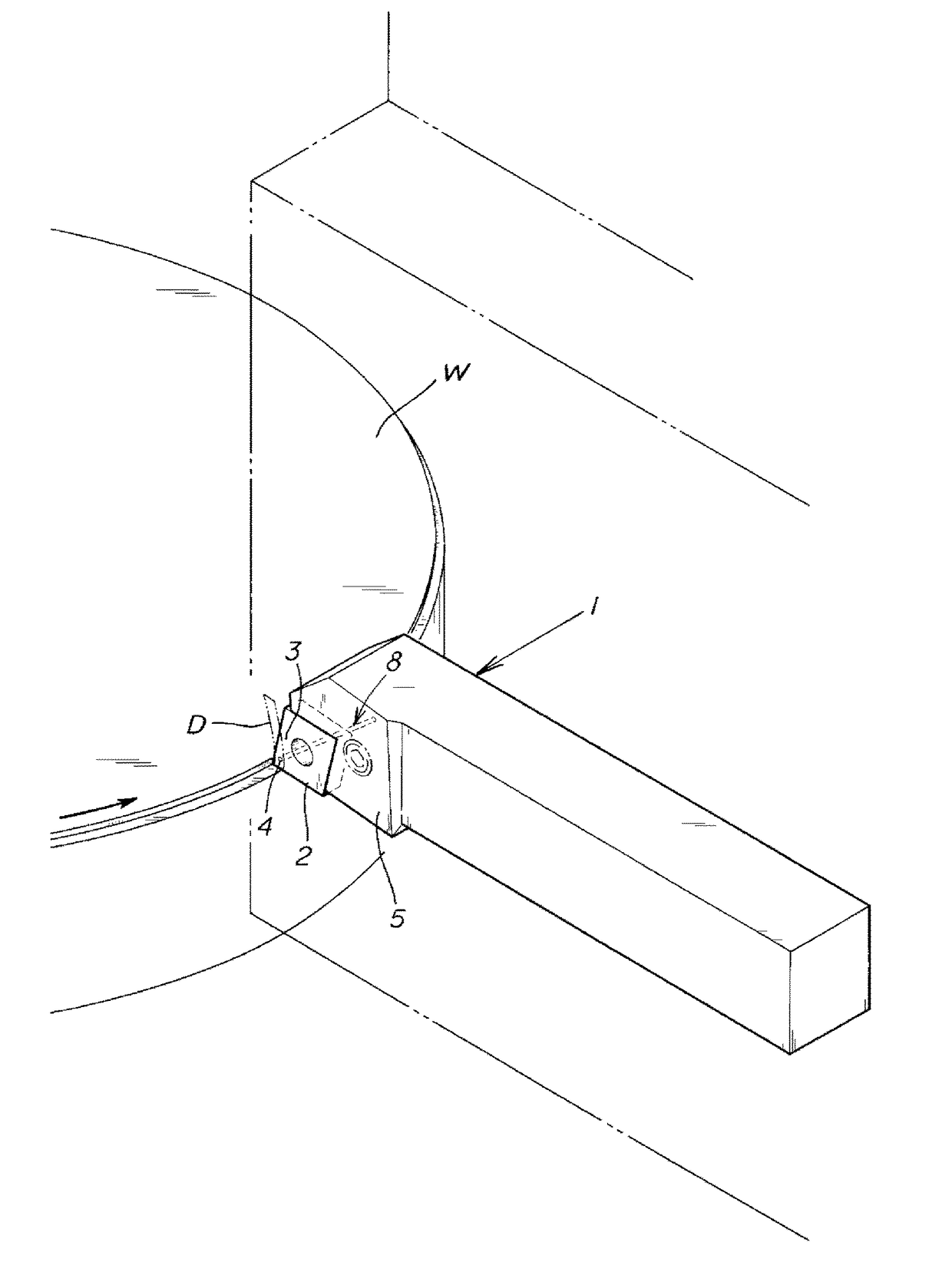
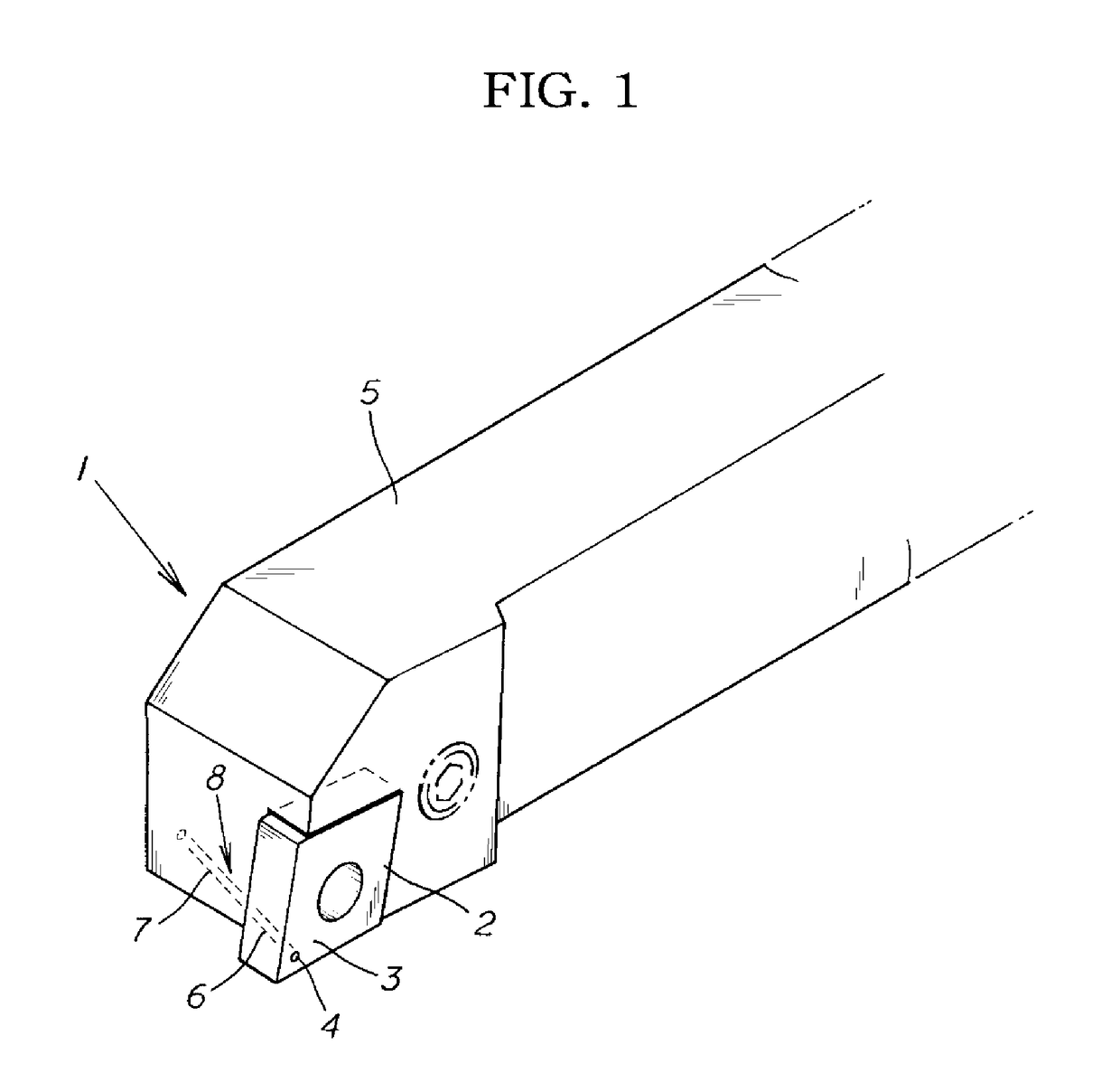
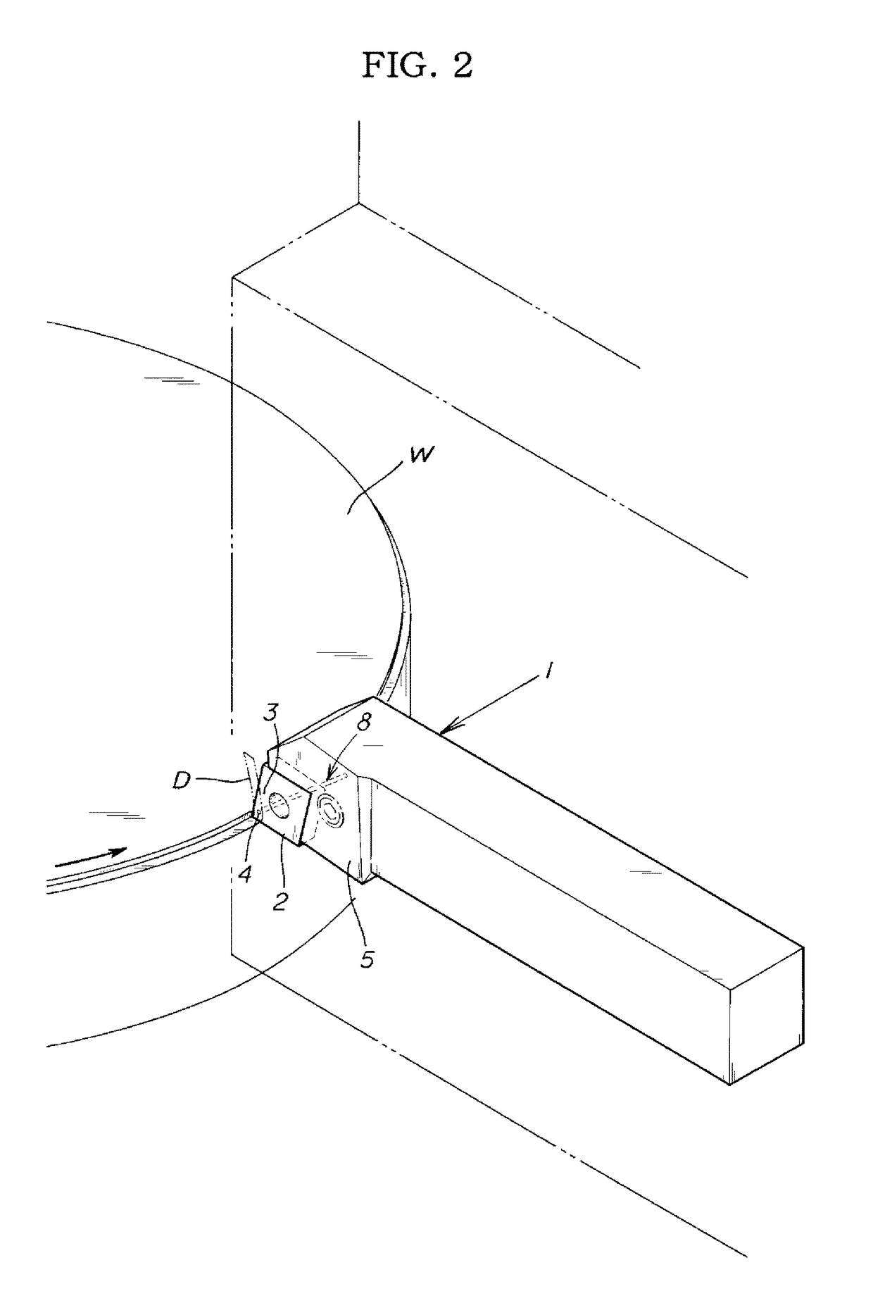
[0028]A specific example of the present invention is described below with reference to the drawings.

[0029]The present example is a lathe-type machine tool for cutting and working a rotating workpiece W using a cutting tool 1 interchangeably mounted on a tool post, wherein a fluid discharge port 4 for discharging a fluid F supplied from a fluid supply unit is provided to a rake surface 3 of a blade tip section 2 provided at a distal end section of the cutting tool 1, which cuts the workpiece W, and the fluid F is discharged from the fluid discharge port 4 toward a rake-surface 3-facing surface of chips D from the workpiece W that slide in pressure contact with the rake surface 3, the fluid F discharged from the fluid discharge port 4 reducing the force with which the chips D that slide in pressure contact with the rake surface 3 make pressure contact with the rake surface 3, and reducing the amount of frictional heat generated by the chips D sliding in pressure contact with the rake ...


PUM


Abstract

A machine tool in which a fluid discharge port (4) for discharging a fluid (F) supplied from a fluid supply unit is provided to a rake surface (3) of a blade tip section (2) provided at a distal end section of the cutting tool (1), which cuts the workpiece (W), and the fluid (F) is discharged from the fluid discharge port (4) toward a rake-surface (2)-facing surface of chips (D) from the workpiece (W) that slide in pressure contact with the rake surface (3), the fluid (F) discharged from the fluid discharge port (4) reducing the force with which the chips (D) that slide in pressure contact with the rake surface (3) make pressure contact with the rake surface (3), and reducing the amount of frictional heat generated by the chips (D) sliding in pressure contact with the rake surface (3).

Description

BACKGROUND OF THE INVENTION1. Field of the Invention[0001]The present invention relates to a lathe, planer, or other machine tool that performs cutting work, and particularly relates to a machine tool having a function for suppressing the increase in temperature to high levels due to the frictional heat of a cutting tool during cutting work.2. Description of the Related Art[0002]In the past, when workpieces have been cut (lathed) using a lathe, planer, or other machine tool, chips that has been cut away from the workpiece slides in pressure contact with the rake surface of a blade tip section of a cutting tool to generate frictional heat. The frictional heat is conducted in distributed fashion to the cutting tool and the chips. The frictional heat conducted to the cutting tool brings the temperature to a high level the cutting tool and particularly the blade tip section to high temperature, and the blade tip section of the cutting tool is softened by the increase to temperatures of ...

Claims


Application Information

Patent Timeline
Patent Type & Authority Applications(United States)
IPC IPC(8): B23B27/10B23Q11/10
CPCB23B27/10B23B2250/12B23Q11/1038B23B27/145
Inventor NAKAMURA, TAKIONAKAKUBO, HIROFUMIGOTO, AKIHIROSEKI, KENSAKU
Owner OM LTD
Why Eureka
Try Eureka