Display device

a technology of display device and light guide plate, which is applied in the direction of optics, instruments, optical light guides, etc., can solve the problems of defective image, increase in material cost and manufacturing steps, and increase in so as to prevent deformation, prevent a defective image in the display device, and reduce the number of manufacturing steps

Active Publication Date: 2018-05-03
LG DISPLAY CO LTD
View PDF2 Cites 4 Cited by
  • Summary
  • Abstract
  • Description
  • Claims
  • Application Information

AI Technical Summary

Benefits of technology

[0016]An object of the the present invention is to provide a display device that is capable of preventing deformation that causes scratching or distortion, or breakage that causes cracks in the light guide plate when the light guide plate is thermally expanded, thereby preventing a defective image in a display device.
[0017]Another object of the present invention is to provide a display device in which a supporting member that supports the light guide plate has a structure capable of being coupled to the cover bottom, the top case, and the like in the display device such that a material cost and the number of manufacturing processes can be reduced, and the assembly of the display device can be simplified.

Problems solved by technology

However, a related art display device as described has a problem in that, when the light guide plate is thermally expanded, the light guide plate may be subjected to deformation that causes scratching or distortion, or subjected to breakage that causes cracks in the light guide plate.
Thus, a defective image may be caused in the display device.
In addition, the related art display device has a problem in that a material cost and the number of manufacturing steps increase due to an assembly structure in which the cover bottom and the top case in which the liquid crystal panel and the light guide plate are built are coupled to each other by separate fastening members.

Method used


Image

  • Display device
  • Display device
  • Display device

Examples


Embodiment Construction

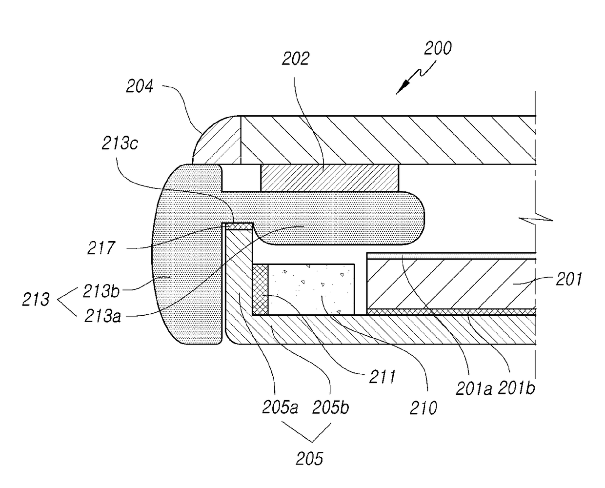
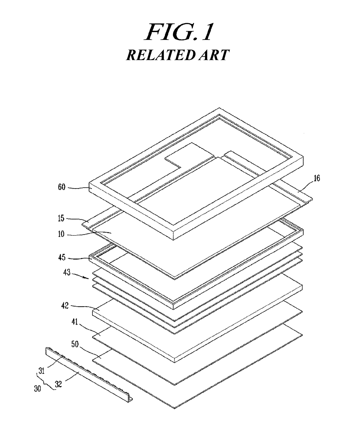
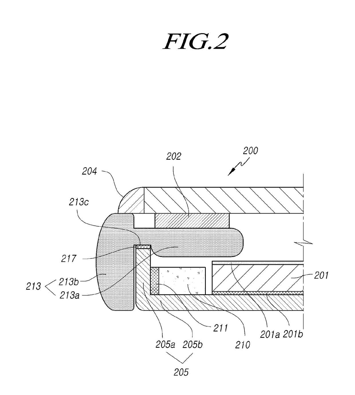
[0026]Hereinafter, embodiments will be described with reference to the accompanying illustrative drawings. In designating elements of the drawings by reference numerals, the same elements will be designated by the same reference numerals although they are shown in different drawings. Further, in the following description of the present invention, a detailed description of known functions and configurations incorporated herein will be omitted when it may make the subject matter of the present invention rather unclear.

[0027]In addition, terms, such as first, second, A, B, (a), (b) or the like may be used herein when describing components of the present invention. Each of these terminologies is not used to define an essence, order or sequence of a corresponding component but used merely to distinguish the corresponding component from other component(s). In the case that it is described that a certain structural element “is connected to,”“is coupled to,” or “is in contact with” another ...


PUM

PropertyMeasurementUnit
inner diameteraaaaaaaaaa
structureaaaaaaaaaa
electric fieldaaaaaaaaaa

Abstract

A display device includes a display panel; a light guide plate configured to provide light to a rear side of the display panel; a cover bottom including a rear portion configured to cover a rear surface of the light guide plate, and a side portion bent toward the display panel from an end portion of the rear portion; and a support coupled to the cover bottom and configured to position the light guide plate and to accommodate longitudinal expansion of the light guide plate, the support being provided at a position adjacent to a longitudinal end portion of the light guide plate.

Description

[0001]This application claims priority from Korean Patent Application No. 10-2016-0143817, filed on Oct. 31, 2016, which is hereby incorporated by reference for all purposes as if fully set forth herein.BACKGROUNDTechnical Field[0002]Embodiments of the present disclosure relate to a display device and, more particularly, to a display device having a display panel and a light guide plate.Description of the Related Art[0003]For use as flat panel display devices, a liquid crystal display device, a plasma display device, a field emission display device, an organic light emitting display device, and the like have been developed. However, the liquid crystal display device and the organic light emitting display device have been in the spotlight in recent years due to advantages of mass production technology, ease in driving, and high image quality.[0004]FIG. 1 is an exploded perspective view illustrating a structure of a general liquid crystal display device.[0005]As illustrated in FIG. 1,...

Claims


Application Information

Patent Timeline
Patent Type & Authority Applications(United States)
IPC IPC(8): G02F1/1335F21V8/00G02F1/1333
CPCG02F1/133524G02B6/0031G02F1/133602G02B6/0016G02F1/133308G02F2001/133314G02B6/0088G02F1/133608G02F1/1336G02B6/0093G02F2201/503G02F2201/54G02B6/0083G02F1/133325G02F1/133317G02F1/133314G02F1/133615G02B6/0086G02F2202/28G02F1/133328G02F1/13332G02F2201/465
Inventor YANG, SANGMOAEO, JONGTAK
Owner LG DISPLAY CO LTD
Why Eureka
Try Eureka