Image exposure device

a technology of exposure device and image, which is applied in the field of image exposure device, can solve the problems of moire between the pitch of the display pixel and the pitch of the optical fiber, the size of the entire device increases, and the device size decreases, so as to prevent damage and favorable image

Active Publication Date: 2020-12-08
FUJIFILM CORP
View PDF10 Cites 0 Cited by
  • Summary
  • Abstract
  • Description
  • Claims
  • Application Information

AI Technical Summary

Benefits of technology

[0009]The present invention has been made in consideration of the above-described circumstance, and an objective of the present invention is to provide an image exposure device capable of recording a favorable image using only light parallel to a photosensitive recording medium from an image display device and capable of decreasing the size of the device. Another objective of the present invention is to provide an image exposure device capable of narrowing an angle at which light radiated from a light source is transmitted, preventing the occurrence of image blurring, preventing damage to a collimator, and preventing a defect in an image to be exposed.
[0011]According to the present invention, by using the louver film in which the light transmitting portions and the light shielding portions are alternately arranged in the first direction and the second direction perpendicular to the first direction, it is possible to block, in light radiated from the pixels, obliquely radiated light that is not parallel to a direction toward the photosensitive recording medium by the light shielding portions. Accordingly, in light radiated from the image display device, only light parallel to the direction toward the photosensitive recording medium can be radiated to the photosensitive recording medium. An image can be recorded on the photosensitive recording medium using only the light parallel to the photosensitive recording medium, and thus it is possible to form a favorable image that is not blurred. In addition, only parallel light is selected using the louver film, whereby a large optical system can be omitted, and the size of the device can be decreased.
[0012]In addition, by providing the protective layer on the louver film on the photosensitive recording medium support portion side, the louver film can be prevented from being damaged by bringing the protective layer into close contact with the photosensitive recording medium during exposure.
[0023]According to this aspect, it is possible to reduce a difference in transmittance between the light of 650 nm and the light of 450 nm radiated from the pixels.
[0031]According to the image exposure device of the present invention, oblique light radiated from the pixels can be blocked by the light shielding portions arranged alternately with the light transmitting portions in the first and second directions. Accordingly, an image can be printed only with light parallel to the photosensitive recording medium, and a favorable image can be formed. In addition, since the protective layer is provided between the louver film and the photosensitive recording medium, the louver film can be prevented from being damaged even in a case where the photosensitive recording medium is repeatedly exposed. Accordingly, an image defect caused by the damage of the louver film can be prevented.

Problems solved by technology

However, in a printing device described in U.S. Pat. No. 9,126,396B, an optical system becomes large, and thus the entire device increases in size, which creates a desire for decreasing the size of the device.
In addition, since the optical fiber array has a structure in which thin optical fibers are bundled, a problem has occurred in that moire occurs between the pixel pitch of the display and the pitch of the optical fibers.
Moreover, it has been difficult to reduce the numerical aperture (NA).
However, in a case where many images are continuously printed, a part of the optical fiber array falls off, and this causes image defects.

Method used


Image

  • Image exposure device
  • Image exposure device
  • Image exposure device

Examples


Embodiment Construction

[0043]Hereinafter, an image exposure device according to an embodiment of the present invention will be described according to the accompanying drawings.

(Image Exposure Device)

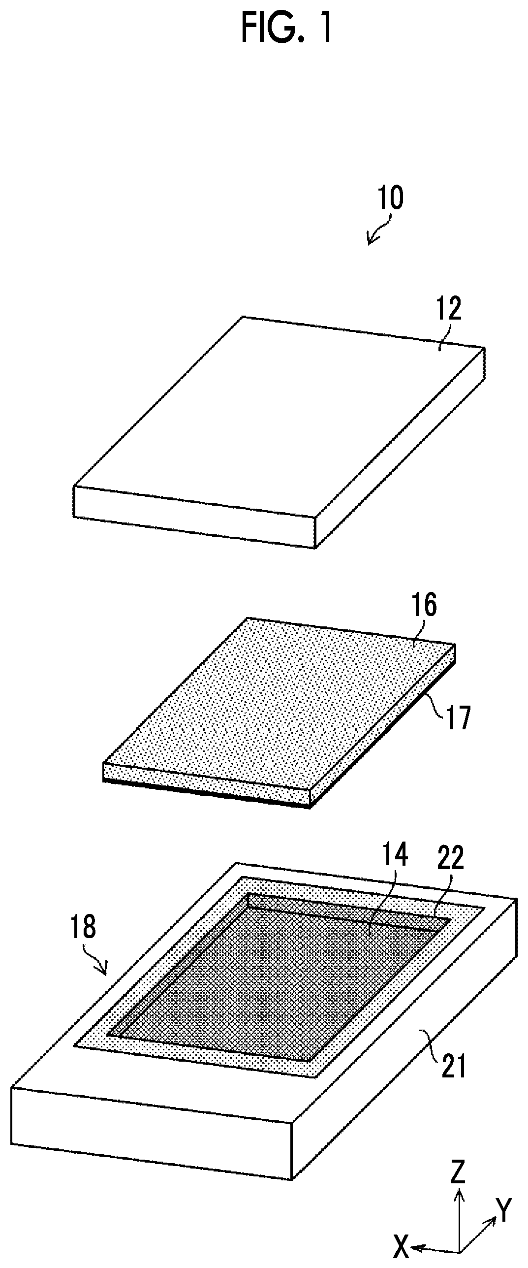
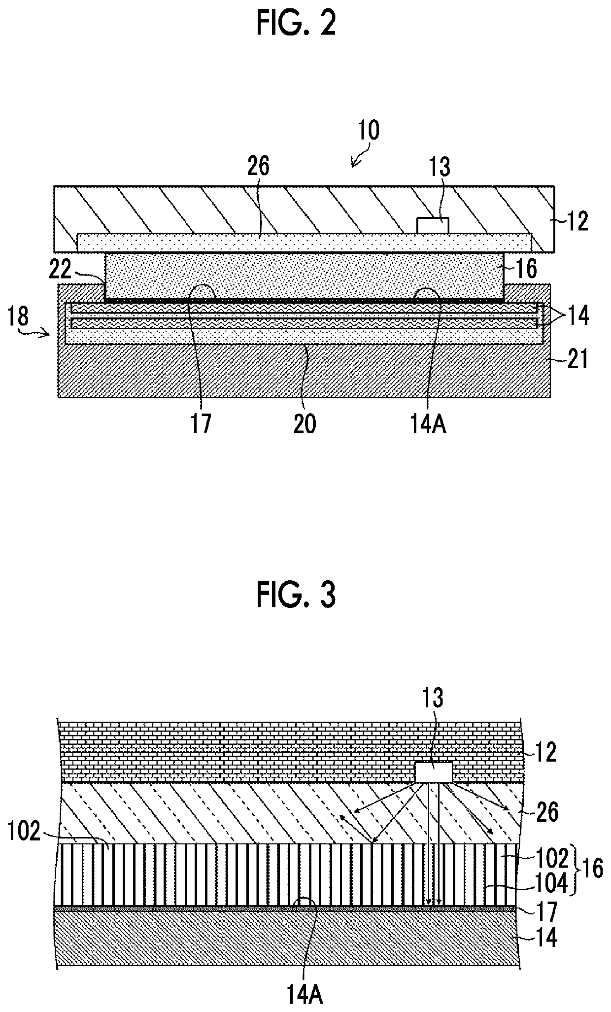
[0044]An image exposure device to which the present invention is applied will be described using FIG. 1 and FIG. 2. FIG. 1 is an exploded perspective view of the image exposure device, and FIG. 2 is a cross-sectional view of the image exposure device.

[0045]An image exposure device 10 in FIGS. 1 and 2 has an image display device 12 having pixels 13, a photosensitive recording medium support portion 21 that supports a photosensitive recording medium 14 for recording an image of the image display device 12, a louver film 16 that is provided between the image display device 12 and the photosensitive recording medium support portion 21, and a protective layer 17 that is provided on the louver film 16 on the side of the photosensitive recording medium support portion 21.

[Image Display Device]

[0046]As the image displ...


PUM

PropertyMeasurementUnit
total thicknessaaaaaaaaaa
thicknessaaaaaaaaaa
angleaaaaaaaaaa

Abstract

An image exposure device includes an image display device having pixels, a photosensitive recording medium support portion that supports a photosensitive recording medium for recording an image of the image display device in a state in which an exposure surface of the photosensitive recording medium faces the image display device, a louver film that is provided between the image display device and the photosensitive recording medium support portion, and in which light transmitting portions that transmit light and light shielding portions that block light are alternately arranged in a first direction, and light transmitting portions that transmit light and light shielding portions that block light are alternately arranged in a second direction, and a protective layer that is provided on the louver film on a side of the photosensitive recording medium support portion.

Description

CROSS-REFERENCE TO RELATED APPLICATIONS[0001]This application is a Continuation of PCT International Application No. PCT / JP2018 / 037049 filed on Oct. 3, 2018, which claims priority under 35 U.S.C § 119(a) to Japanese Patent Application No. 2017-214563 filed on Nov. 7, 2017. Each of the above applications is hereby expressly incorporated by reference, in its entirety, into the present application.BACKGROUND OF THE INVENTION1. Field of the Invention[0002]The present invention relates to an image exposure device and particularly to an image exposure device that selects, in light radiated from a light source, light parallel to a photosensitive recording medium for recording an image and carries out exposure using the light.2. Description of the Related Art[0003]For the exposure of photographs, photomasks, or the like, optical systems for projecting that are optical systems of an imaging system are being used. However, in the case of the optical systems for projecting, an optical system s...

Claims


Application Information

Patent Timeline
Patent Type & Authority Patents(United States)
IPC IPC(8): B41F17/00G02B27/09G02B27/30
CPCG02B27/0988B41F17/00G02B27/30G02B2207/123G02B5/00G03F7/2051
Inventor USAMI, YOSHIHISASONODA, SHINICHIROYOSHIZAWA, HIROTOSHI
Owner FUJIFILM CORP
Why Eureka
Try Eureka