Improved apparatus for temperature measurement and control using two wires per thermal zone and methods of use

a technology of temperature measurement and control apparatus, applied in the field of temperature measurement and control, can solve the problems of poor accuracy, low accuracy, and no means for the user to monitor the temperature, and achieve the effect of high accuracy and insensitive to background noise and/or biases

Inactive Publication Date: 2018-06-28
ADAMSON ADRIAN M
View PDF4 Cites 0 Cited by
  • Summary
  • Abstract
  • Description
  • Claims
  • Application Information

AI Technical Summary

Benefits of technology

[0007]The present inventive disclosures are generally directed to an improved means to precisely measure temperature at a location remote from a central controller and a means to control heater and/or cooler power at that remote location with a temperature setpoint that is adjustable at the central-controller location, with a remote device/unit connected to the central controller using no more than two wires. The remote unit uses the level of the input voltage from the central controller to switch between communicating high-accuracy

Problems solved by technology

However, these suffer the drawback of a fixed, low-accuracy temperature setpoint, and provide no means for the user to monitor the temperature.
This approach suffers the drawbacks of poor accuracy due to biases caused by wiring/harness resistance, high/excessive power consumption during temperature measurement, limitations on the useful range of allowable heater resistance, and limitations on the heater material that can be used to those which significantly change resistance over the temperature range of interest.
Because of the aforementioned difficulties with measurement accuracy, this approach is typically limited to applications in which an absolute temperature measurement is not necessary, and the heater setpoint can be selected with an in-situ calibration.
The drawback with this approach is that using more than two wires between a central controller and its various remote thermal-control zones adds cost, size, and mass which is especially critical for mass-sensitive

Method used


Image

  • Improved apparatus for temperature measurement and control using two wires per thermal zone and methods of use
  • Improved apparatus for temperature measurement and control using two wires per thermal zone and methods of use
  • Improved apparatus for temperature measurement and control using two wires per thermal zone and methods of use

Examples


Embodiment Construction

I. Overview

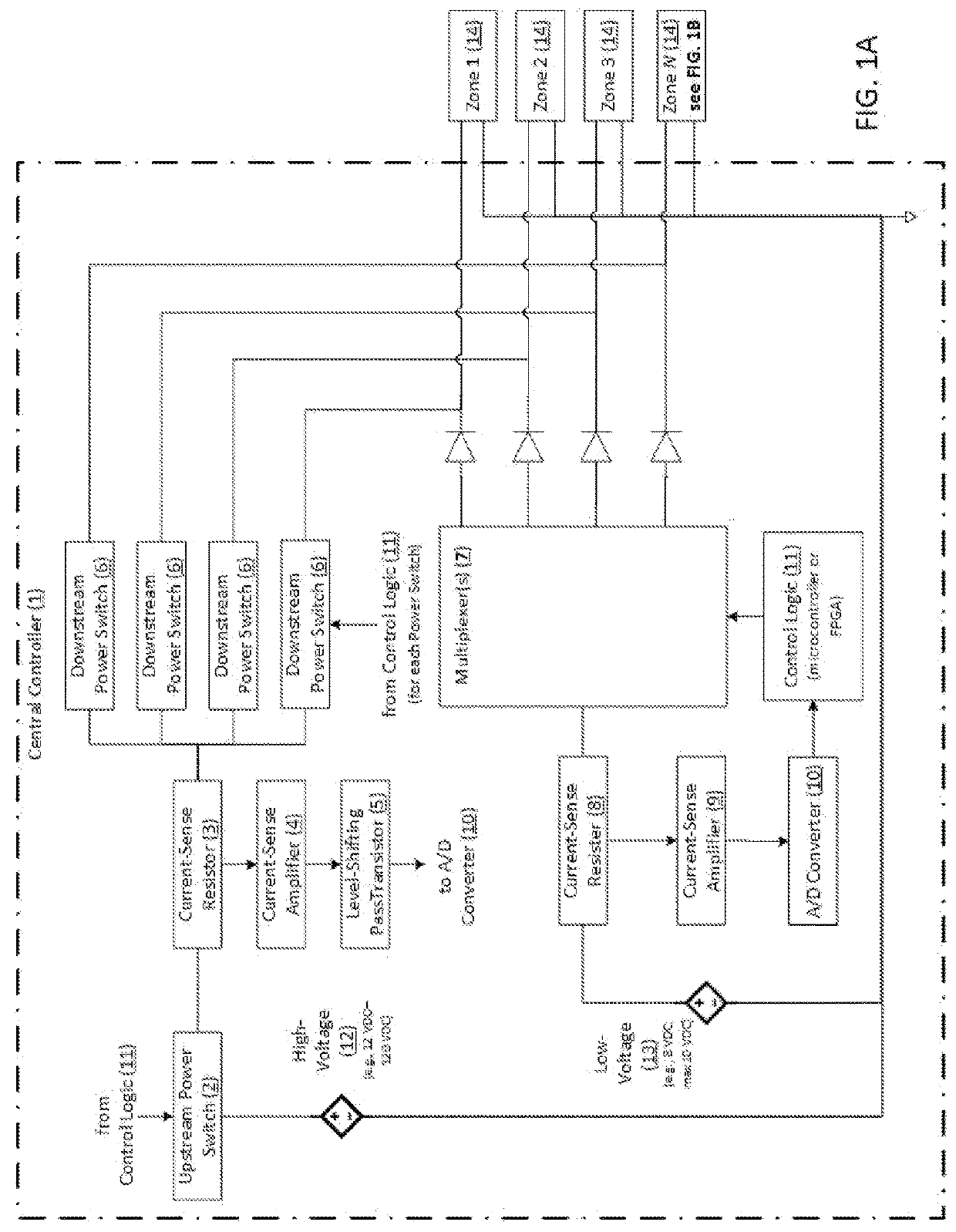
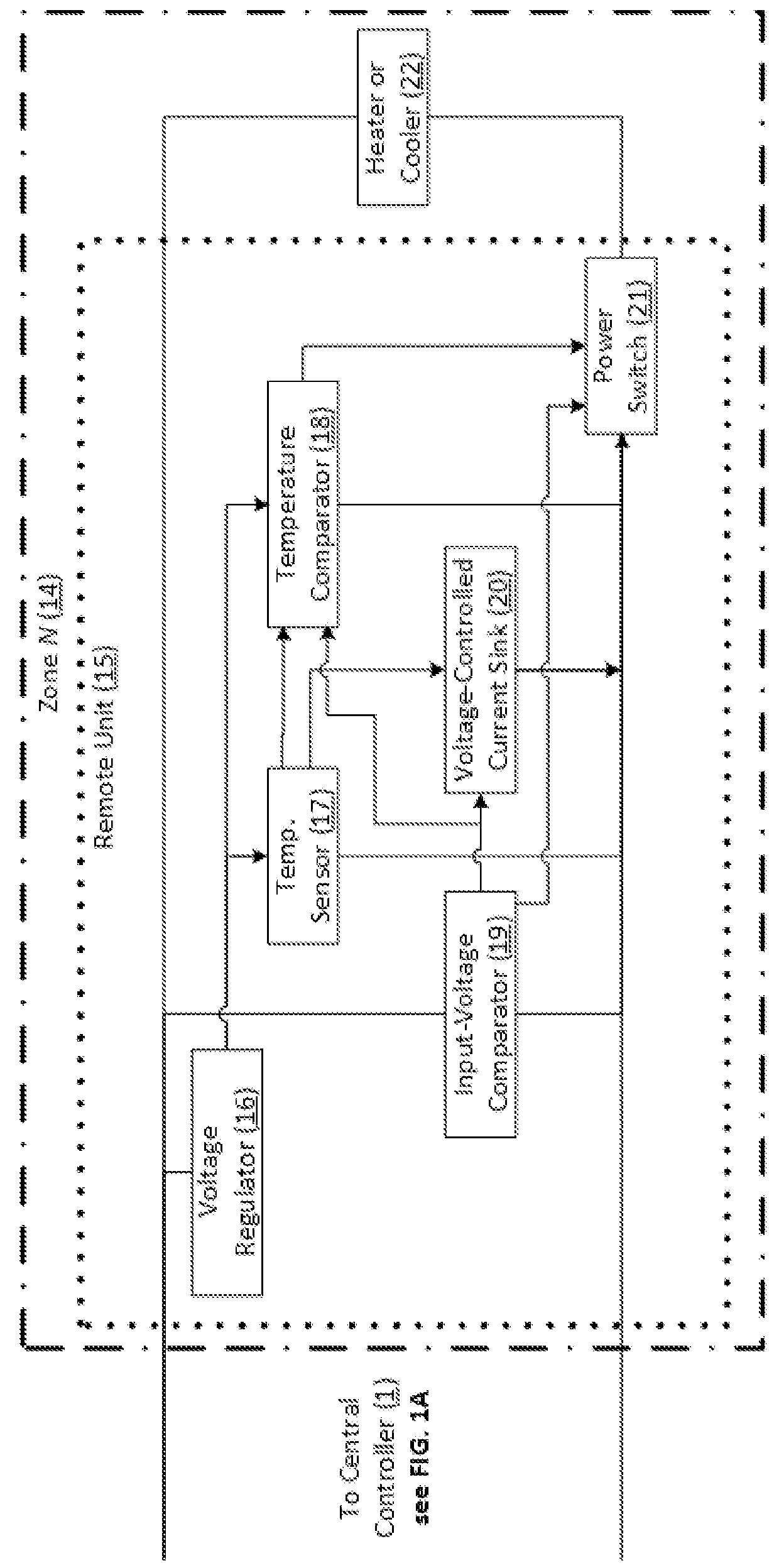
[0015]The present inventive disclosures are generally directed to an improved means to precisely measure temperature at a location remote from a central controller and a means to control heater and / or cooler power at that remote location with a temperature setpoint that is adjustable at the central-controller location, with a remote device / unit connected to the central controller using no more than two wires. The remote unit uses the level of the input voltage from the central controller to switch between communicating high-accuracy instrumentation signals from a temperature sensor disposed at the remote unit back to the central controller and passing power to the heater and / or cooler device at or in the remote unit. The temperature-sensing function provides higher accuracy than previous implementations of two-wire zones because its electrical signal is in the form of a controlled current, which is both unaffected by the wire resistance, and is relatively insensitive to b...


PUM


Abstract

The present inventive disclosures are generally directed to an improved means to precisely measure temperature at a location remote from a central controller and a means to control heater and/or cooler power at that remote location with a temperature setpoint that is adjustable at the central-controller location, with a remote device/unit connected to the central controller using no more than two wires, employing specialized time-sliced alternating operating modes via those two wires in which high-accuracy current-based temperature readings are transmitted back to a central controller in one mode, and thermal-device power is provided in the other mode. The improved system is, as a result, both very cost-efficient and mass-efficient for controlling a multitude of thermal zones.

Description

CROSS-REFERENCE TO RELATED APPLICATIONS[0001]This patent application claims the priority benefit of U.S. Patent Application No. 62 / 193,042, filed on Jul. 15, 2015 for “Temperature measurement and control using 2 wires per thermal zone”, and incorporates by reference U.S. Patent Application No. 62 / 193,042 in its entirety herein for all purposes.BACKGROUND[0002]The inventive disclosure contained herein relates to various applications of temperature measurement and control via electric heaters (or in some cases cooling configurations) abound throughout all of industry, from consumer goods such as electric blankets to petrochemical processing, to spacecraft thermal control. These diverse applications are tied together by the need to measure a temperature and provide controlled electrical power for heating and / or cooling based on that temperature. A heater and / or cooler, temperature sensing device, and the thermally conductive structure connecting them can be referred to as a “thermal zo...

Claims


Application Information

Patent Timeline
IPC IPC(8): H05B1/02G05D23/19G08C19/02
CPCH05B1/0288G05D23/1917G08C19/02B64G1/50G05D23/1934B64G1/00H05B1/02
Inventor ADAMSON, ADRIAN M.
Owner ADAMSON ADRIAN M
Why Eureka
Try Eureka